
Novel stator and rotor structure of switched reluctance motor

A switched reluctance motor, stator and rotor technology, applied in the magnetic circuit shape/style/structure, magnetic circuit rotating parts, AC motor control, etc., can solve the problem of temperature rise, affect the life of the motor, reduce the safety of the motor, etc. , to achieve the effects of reducing torque ripple, reducing the magnetic density at the pole-to-pole endpoints, and improving the effect of excessive temperature rise

Pending Publication Date: 2021-03-30
HARBIN UNIV OF SCI & TECH
View PDF0 Cites 2 Cited by
  • Summary
  • Abstract
  • Description
  • Claims
  • Application Information

AI Technical Summary

Problems solved by technology

[0003] Different from the working mode of the traditional motor, since the double salient pole structure of the switched reluctance motor adopts the "minimum reluctance principle", it will inevitably produce a large rotational speed while generating a large starting torque and average torque. Torque ripple; on the other hand, due to the characteristics of the operation mode, the magnetic density between the poles of the stator and rotor is too large, and the phenomenon of temperature rise is obvious, which reduces the safety of the motor and affects the life of the motor. Therefore, it is proposed to reduce the torque ripple of the motor and reduce the A New Structure of Magnetic Density Between Poles

Method used


Image

  • Novel stator and rotor structure of switched reluctance motor
  • Novel stator and rotor structure of switched reluctance motor
  • Novel stator and rotor structure of switched reluctance motor

Examples


Embodiment Construction

[0013]The present invention will be further described below with reference to the accompanying drawings.

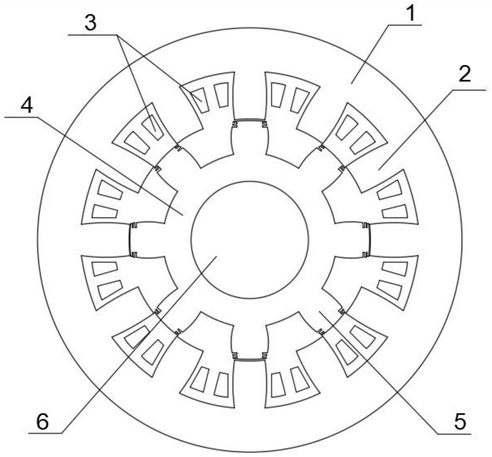
[0014]Referfigure 1 As shown, the three-phase 12 / 8 pole switching magnetic blocking motor is designed, the motor structure is a double male polar structure, the stator is outside, the rotor, the windings are centralized windings, mounted on the stator teeth.

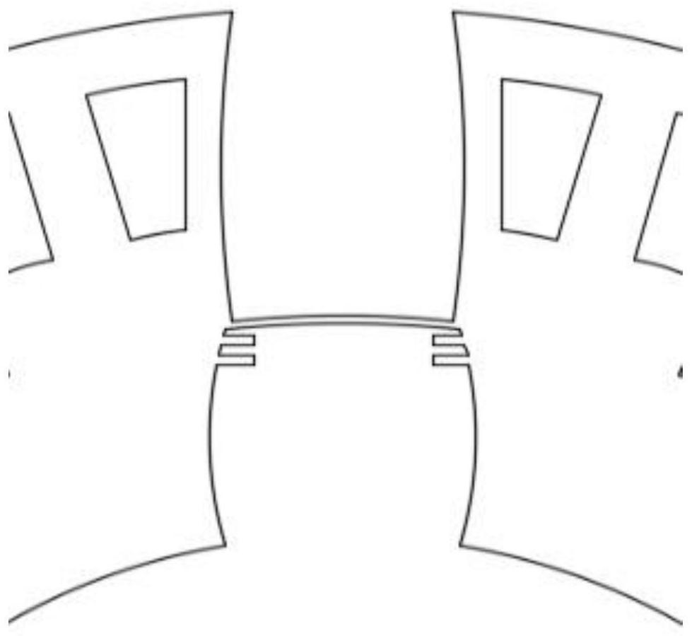
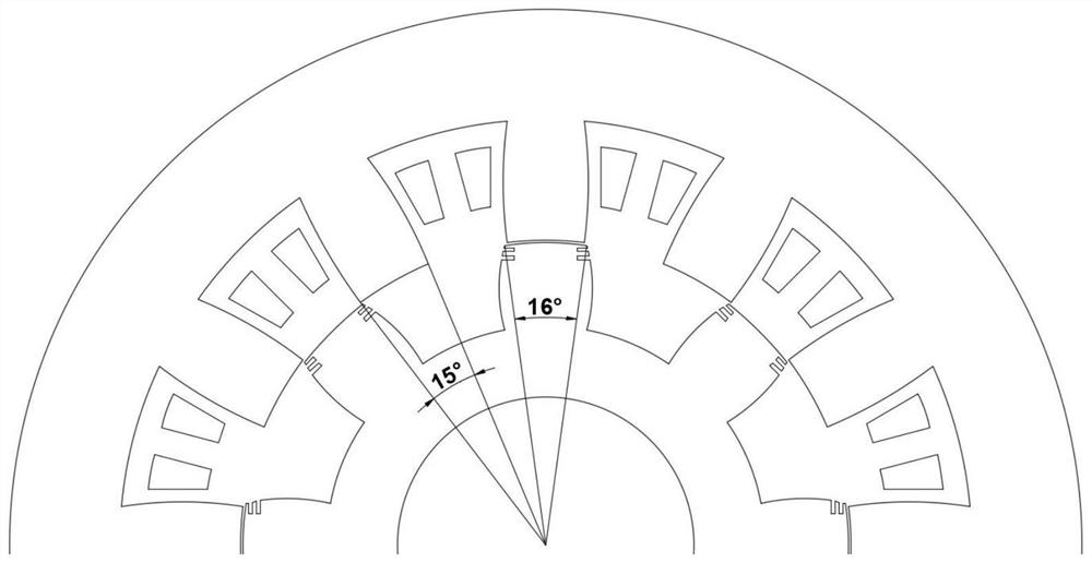
[0015]Referfigure 2 As shown, for the stator: the curved teeth of the motor stator compresses the stator groove space, which can increase the tank manifest, enhance the heat dissipation function of the motor;, due to the widening of the magnetic passage, the magnetic magnetic can be reduced. Military waveform.

[0016]Referfigure 2 As shown, for the rotor: Since the edge magnetic flux is an important reason that causes the motor torque pulsation, the edge magnetic flux will be generated before the rotor is coincident, so two rectangular grooves are opened on both sides of the rotor tooth. This structure can reduce the edge magneti...


PUM


Abstract

The invention relates to a novel stator and rotor structure of a switched reluctance motor, and belongs to the technical field of motor structures. A motor body comprises a stator, a winding and a rotor, and a motor structure with the stator arranged outside and the rotor arranged inside is adopted; the stator is composed of stator teeth and a stator yoke, the twelve stator teeth are arranged in the stator yoke at equal intervals in the circumferential direction, unequal-width thickening treatment is conducted on the two sides of the stator teeth, the inter-pole endpoint flux density can be reduced when the stator and the rotor are tangent in the operation process of the motor, and the overall temperature of the motor can be reduced. Winding connection is installed on the stator teeth in aconcentrated winding mode. The eight rotor teeth are distributed on the outer portion of the rotor yoke at equal intervals in the circumferential direction, the two sides of the tooth body are thickened in an unequal-width mode, meanwhile, the two sides of the tooth top are each provided with two symmetrical rectangular grooves, and therefore the radial air gap flux density can be increased, thetangential flux density can be reduced, the average torque of the motor can be increased, and torque pulsation can be reduced.

Description

Technical field[0001]The present invention relates to the technical field of motor structure, and is a novel switching magnetic resistance electromechanical electromechanical structure.Background technique[0002]The switching magnetic blocking motor is widely used in various fields such as aerospace, ship, mining mining and industrial and agricultural production due to its unique double projection rotor structure. Switch magnetic resistor motor has many advantages over the traditional asynchronous motor: the start torque is large, the efficiency is high, the speed can be good, and the forward and reverse speed is simple. It can operate at a long time; the structure is simple, no winding on the rotor The stator windings use a centralized distribution, simple wiring, easy to exclude, from engineering cost and maintenance, can save a lot of cost and operation and maintenance overhead. Therefore, since high-efficiency and energy-saving new ideas have become the mainstream development dir...

Claims


Application Information

Patent Timeline
Patent Type & Authority Applications(China)
IPC IPC(8): H02K1/14H02K3/28H02K1/24H02K3/12H02K3/48H02P25/098
CPCH02K1/146H02K3/28H02K1/24H02K3/12H02K3/48H02P25/098H02K2201/03H02K2213/03
Inventor 戈宝军范家成张梦娜
Owner HARBIN UNIV OF SCI & TECH
Learn More