Novel hot end trimming and punching die

A technology of edge trimming, punching and hot end, applied in the field of metal stamping dies, which can solve the problems of increased labor cost, machine use, uneven product cut surface, and deviation of positioning reference, so as to reduce labor cost and machine use, and improve the quality of cut surface , to ensure the effect of stability

Inactive Publication Date: 2021-04-02
爱驰威汽车零部件(盐城)有限公司
View PDF5 Cites 0 Cited by
  • Summary
  • Abstract
  • Description
  • Claims
  • Application Information

AI Technical Summary

Problems solved by technology

Because there are multiple molds in the multi-process side punching, the positioning reference is deviated, resulting in uneven steps on the cut surface of the product
Another way is to use a single punch for direct punching, which will cause the two sides of the product to be squeezed because the punching surface is close to vertical, and the material will be squeezed, causing serious burrs on the product; at the same time, multi-process processing will undoubtedly increase labor costs and use of machines. have a certain impact on the economic benefits of

Method used


Image

  • Novel hot end trimming and punching die
  • Novel hot end trimming and punching die
  • Novel hot end trimming and punching die

Examples


Embodiment Construction

[0031] The technical solutions in the embodiments of the present invention will be clearly and completely described below with reference to the accompanying drawings in the embodiments of the present invention. Obviously, the described embodiments are only a part of the embodiments of the present invention, but not all of the embodiments. Based on the embodiments of the present invention, all other embodiments obtained by those of ordinary skill in the art without creative efforts shall fall within the protection scope of the present invention.

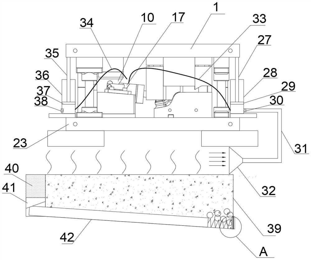
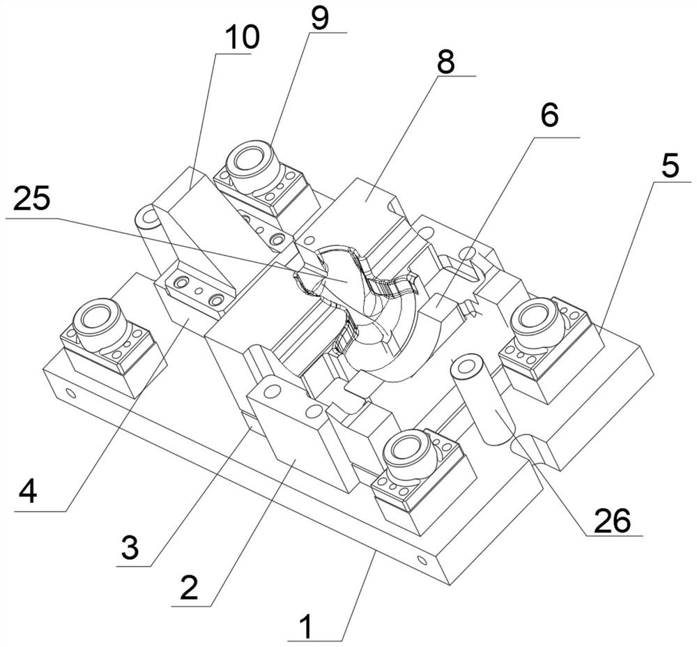
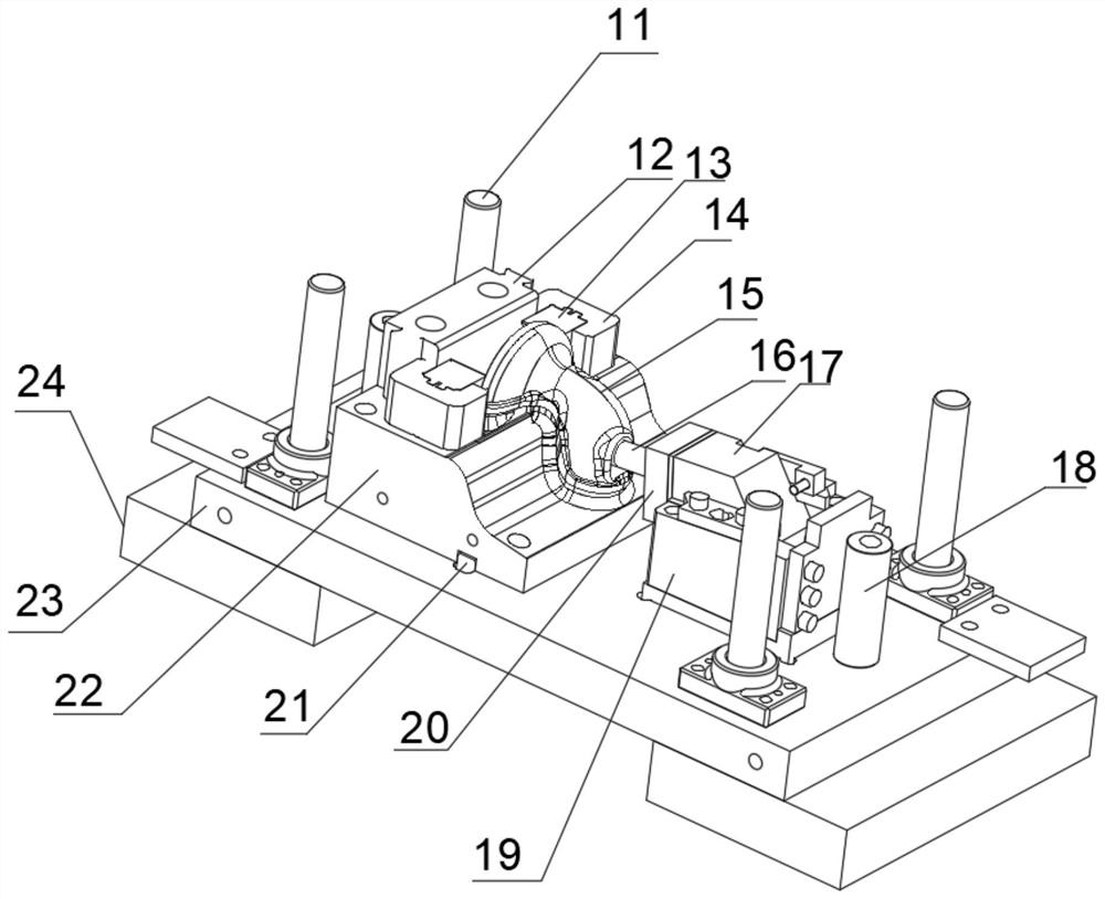
[0032] see Figure 1-5 , the present invention provides technical scheme: as figure 2 , a new type of hot-end trimming and punching die, including an upper die base 1 and a lower die base 23, characterized in that: the four corners of the upper die base 1 are provided with guide post spacers 5, and above the guide post spacer 5 are provided with outer The guide sleeve 9, the upper mold seat 1 is provided with an upper limit column 2...


PUM


Abstract

The invention discloses a novel hot end trimming and punching die. The novel hot end trimming and punching die comprises an upper die base and a lower die base and is characterized in that guide column cushion blocks are arranged at four corners of the surface of the upper die base, outer guide sleeves are arranged above the guide column cushion blocks, upper limiting columns are arranged betweentwo sides of the surface of the upper die base, slotting tool fixing blocks are arranged on the surface of an upper die, a slotting tool is fixedly arranged above the slotting tool fixing block and isin a slope triangular block shape, an upper clamping plate is arranged on one side of the slotting tool fixing block, guiding blocks are fixedly arranged on two sides of the upper clamping plate, anupper stripping plate is arranged above the upper clamping plate, an upper die groove is formed in the upper stripping plate, an upper die punch is arranged on one side of the upper stripping plate, the upper die punch penetrates through the upper stripping plate and is fixed on the upper clamping plate, foot pads are arranged on two sides of the lower side of a lower die plate, outer guide columns are arranged at four corners of the surface of the lower die base, and the outer guide columns and the outer guide sleeves are of matched structures. The novel hot end trimming and punching die hasthe advantages of being high in production efficiency, good in quality durable.

Description

technical field [0001] The invention relates to the technical field of metal stamping dies, in particular to a novel hot-end trimming and punching die. Background technique [0002] Stamping die is a special process equipment that processes materials (metal or non-metal) into parts (or semi-finished products) in cold stamping, called cold stamping die (commonly known as cold stamping die). Stamping is a pressure processing method that uses a die installed on a press to apply pressure to a material at room temperature to separate or plastically deform it to obtain the required parts. [0003] The existing design adopts multi-process side punching to achieve the shearing of the semicircle. Alternatively, a single punch cuts the edge directly. The multi-process side punch has multiple dies, so the positioning reference is deviated, resulting in uneven steps on the cut surface of the product. Another way is to use a single punch to directly punch, which will cause the two sid...

Claims


Application Information

Patent Timeline
Patent Type & Authority Applications(China)
IPC IPC(8): B21D28/34B21D28/14B21D37/10B21D37/16B08B5/02B08B15/04F24F6/02B01D47/02
CPCB21D28/34B21D28/14B21D37/10B21D37/16B08B5/02B08B15/04F24F6/02B01D47/02
Inventor 胡勇许海伟徐海洋
Owner 爱驰威汽车零部件(盐城)有限公司
Why Eureka
Try Eureka