Welding equipment for air extraction hole in bottom of vacuum cup and machining process of welding equipment

A technology of welding equipment and processing technology, which is applied in the field of welding equipment and processing technology of the vacuum hole at the bottom of the thermos cup, can solve the problems that affect the yield of the thermos cup, and it is difficult to ensure that the vacuum hole is completely blocked, so as to ensure safety and Convenience, stable vacuum sealing, and the effect of ensuring welding stability

Pending Publication Date: 2021-04-02
浙江裕川工贸有限公司
View PDF6 Cites 5 Cited by
  • Summary
  • Abstract
  • Description
  • Claims
  • Application Information

AI Technical Summary

Problems solved by technology

[0007] The manufacturing process of the thermal insulation titanium cup disclosed above uses brazing material to weld and seal the vacuum hole at the bottom of the thermal insulation cup. Since the brazing material needs to be melted during the welding process, the shape of the brazing material after cooling and solidification is: Irregular shape, which makes it necessary to polish the cooled brazing material after welding and sealing with the brazing material, so that the bottom of the thermos cup is flat, and at the same time, it is difficult for the molten brazing material to ensure the complete sealing of the vacuum hole. Affect the yield of the thermos cup

Method used


Image

  • Welding equipment for air extraction hole in bottom of vacuum cup and machining process of welding equipment
  • Welding equipment for air extraction hole in bottom of vacuum cup and machining process of welding equipment
  • Welding equipment for air extraction hole in bottom of vacuum cup and machining process of welding equipment

Examples


Embodiment Construction

[0035] Embodiments of the present invention will be described in detail below in conjunction with the accompanying drawings.

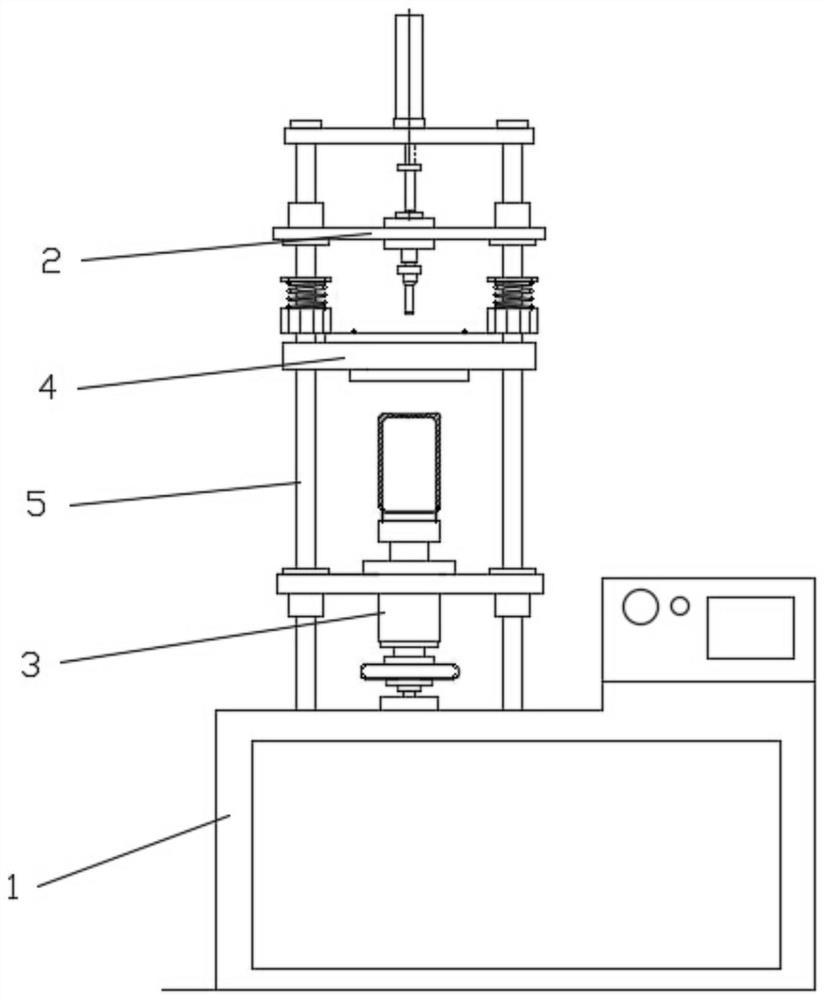
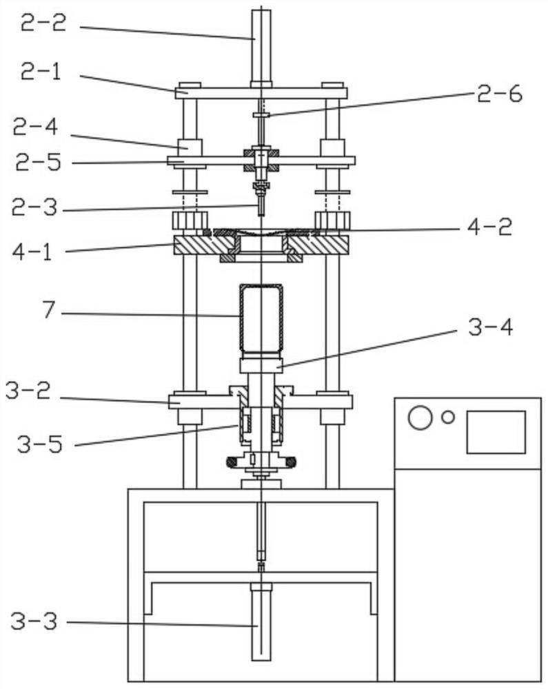
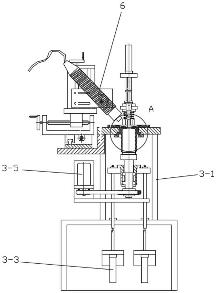
[0036] Such as Figure 1-7 As shown in the figure, a welding device for the air extraction hole at the bottom of a thermos cup includes a frame base 1, and a corresponding top pressing device 2, a bottom lifting and rotating device 3 and a guiding device are arranged on the frame base 1 from top to bottom. 4. The top pressing device 2 and the bottom lifting and rotating device 3 are movably connected to the frame base 1, and both the top pressing device 2 and the bottom lifting and rotating device 3 move toward the direction of the guide device 4; the guide device 4 includes a horizontally arranged fixed plate 4-1, the middle part of the fixed plate 4-1 is formed with a downwardly arranged conical surface 4-2, and the middle part of the conical surface 4-2 is formed with a through hole; the frame base 1 is also provided with a laser welding device 6, l...


PUM


Abstract

The invention relates to welding equipment for an air extraction hole in the bottom of a vacuum cup and a machining process of the welding equipment. The welding equipment comprises a machine frame base, wherein the machine frame base is provided with a top pressing device, a bottom lifting and rotating device and a guiding device which correspond to one another from top to bottom, and the top pressing device and the bottom lifting and rotating device are movably connected to the machine frame base; the top pressing device and the bottom lifting and rotating device move towards the guiding device; and the guiding device comprises a horizontally-arranged fixing plate, a conical surface arranged downwards is formed in the middle of the fixing plate, and a through hole is formed in the middleof the conical surface. Compared with the prior art, the welding equipment has the advantages that through the arrangement of the bottom lifting and rotating device and the guiding device, the to-be-welded position of the bottom of the vacuum cup is moved to the bottom of the conical surface of the guiding device, and the welding piece is moved to the to-be-welded position of the bottom of the vacuum cup under the action of gravity and the conical surface, so that the safety and the convenience of the welding process are ensured; and besides, the top pressing device is arranged to press the welding piece compactly, so that the welding stability of the welding piece and the vacuum cup is ensured.

Description

technical field [0001] The invention belongs to the technical field of thermos cup processing, in particular to a welding device and a processing technology for a vacuum hole at the bottom of a thermos cup. Background technique [0002] The stainless steel thermos cup is made of double-layer stainless steel inside and outside. The inner tank and the outer shell are combined by welding technology, and the air in the interlayer between the inner tank and the outer shell is extracted by vacuum technology to achieve the effect of vacuum insulation. [0003] The vacuum equipment used in the society for vacuuming vacuum flasks includes vacuum exhaust tables and vacuum brazing furnaces, and there are about two types and four types. One type is the desktop type with tail vacuum exhaust; the other type is the type of brazing furnace. The brazing furnace type is divided into: single chamber, multi-chamber, and multi-chamber with increased pumping speed. [0004] In the vacuuming pro...

Claims


Application Information

Patent Timeline
Patent Type & Authority Applications(China)
IPC IPC(8): B23K26/02B23K26/21B23K26/70
CPCB23K26/21B23K26/702B23K26/02
Inventor 张如平
Owner 浙江裕川工贸有限公司
Why Eureka
Try Eureka