Industrial wire drawing equipment for surface of metal disc

A metal disc and surface drawing technology, which is applied in metal processing equipment, grinding/polishing equipment, manufacturing tools, etc., can solve the problems of low quality of disc drawing, long time consumption, low work efficiency, etc., and achieve convenience Effects of collection, reduction of cost loss, and improvement of processing efficiency

Active Publication Date: 2021-04-02
平阳县金锋金属制品有限公司
View PDF10 Cites 0 Cited by
  • Summary
  • Abstract
  • Description
  • Claims
  • Application Information

AI Technical Summary

Problems solved by technology

[0005] In order to overcome the shortcomings of the low quality of the wire drawing of the disc, which will easily lead to an increase in cost, a long time consumption, and low work efficiency, the technical problem to be solved is: to provide an automatic wire drawing of the metal disc with high work efficiency. Industrial wire drawing equipment for the surface of metal discs

Method used


Image

  • Industrial wire drawing equipment for surface of metal disc
  • Industrial wire drawing equipment for surface of metal disc
  • Industrial wire drawing equipment for surface of metal disc

Examples


Embodiment 1

[0066] An industrial wire drawing equipment for the surface of metal discs, such as figure 1 As shown, it includes a base 1, a pushing mechanism 2, an abrasive belt drawing mechanism 3 and a sand pressing mechanism 4. The left side of the base 1 is provided with a pushing mechanism 2, and the base 1 is provided with an abrasive belt drawing mechanism 3. A sand pressing mechanism 4 is provided between the base 1 and the pushing mechanism 2 .

[0067] When people need to process the surface of the metal disc, people place the metal disc in the pusher mechanism 2. At this time, people open the pusher mechanism 2 and the abrasive belt drawing mechanism 3, so that the pusher mechanism 2 pushes the metal disc Push it to the right, and then push the metal disc to the bottom of the abrasive belt wire drawing mechanism 3. Since the pushing mechanism 2 moves to the right, the sand pressing mechanism 4 moves to the right, and then the sand pressing mechanism 4 pushes the abrasive belt wi...

Embodiment 2

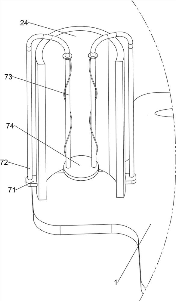
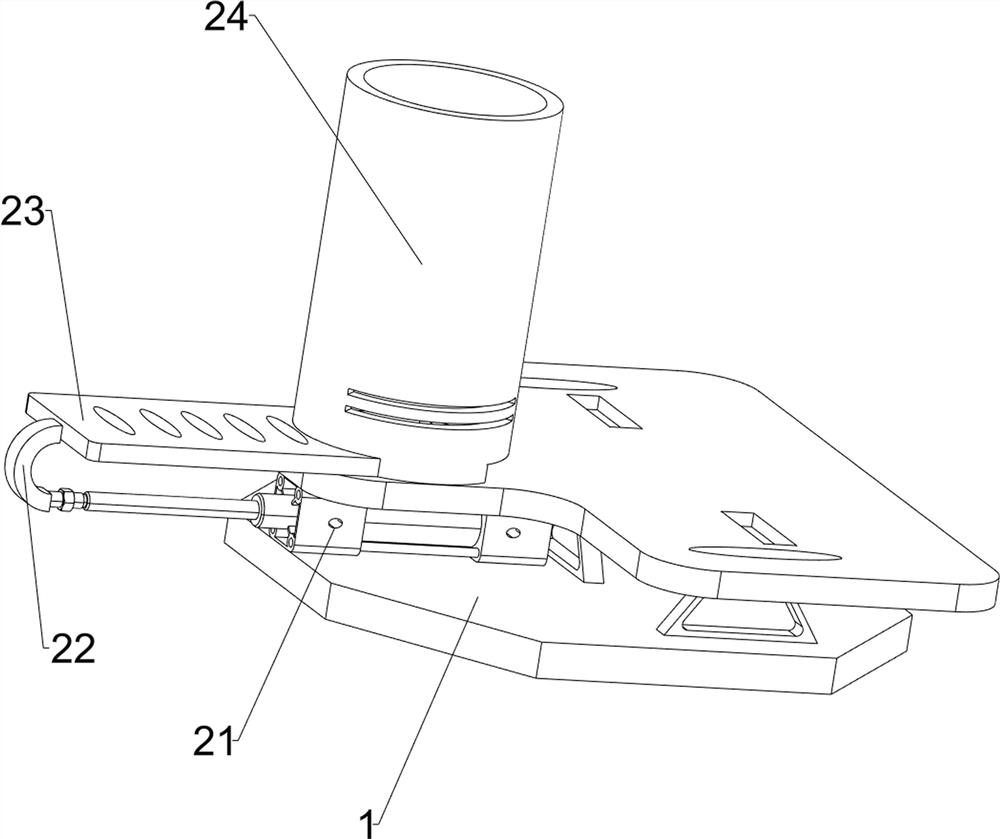
[0069] On the basis of Example 1, such as figure 2 As shown, the pushing mechanism 2 includes a cylinder 21, an arc-shaped connecting rod 22, a push plate 23 and a feeding box 24, the left side of the base 1 is provided with a cylinder 21, and the output shaft of the cylinder 21 is connected with an arc-shaped connecting rod 22 , The right end of the arc-shaped connecting rod 22 is provided with a push plate 23, the push plate 23 is slidably connected with the base 1, and the upper left side of the base 1 is provided with a blanking box 24.

[0070] When people need to process metal discs, they place the metal discs in the blanking box 24. At this time, the metal discs are located on the base 1, and people open the cylinder 21 so that the output shaft of the cylinder 21 drives the arc connection. The rod 22 moves to the right, and then drives the push plate 23 to move to the right, so that the push plate 23 pushes the metal disc to move to the right, pushes the metal disc to ...

Embodiment 3

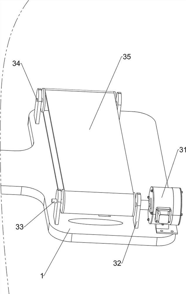
[0072] On the basis of Example 2, such as figure 1 , Figure 3-Figure 7 As shown, the abrasive belt wire drawing mechanism 3 includes a motor 31, a first bearing seat 32, a first rotating shaft 33, a second rotating shaft 34 and a rotating abrasive belt 35, and the right front portion on the base 1 is provided with a motor 31, and the base 1 The first bearing seat 32 is symmetrically arranged on the front, rear, left and right sides, and the first rotating shaft 33 is arranged in a rotating manner between the two first bearing seats 32 on the front side. The first rotating shaft 33 is connected with the output shaft of the motor 31. A second rotating shaft 34 is rotatably arranged between the first bearing seats 32, and a rotating abrasive belt 35 is wound between the first rotating shaft 33 and the second rotating shaft 34.

[0073] When the push plate 23 pushes the metal disk under the rotating abrasive belt 35, people turn on the motor 31, so that the output shaft of the m...


PUM


Abstract

The invention relates to surface wire drawing equipment, in particular to industrial wire drawing equipment for the surface of a metal disc. The industrial wire drawing equipment for the surface of the metal disc provided by the invention automatically conducts wire drawing on the metal disc and is high in working efficiency. The industrial wire drawing equipment for the surface of the metal disccomprises a base and a pushing mechanism, an abrasive belt wire drawing mechanism and a sand pressing mechanism, and the pushing mechanism is arranged on the base; the abrasive belt wire drawing mechanism is arranged on the base; and the sand pressing mechanism is arranged between the base and the pushing mechanism. According to the industrial wire drawing equipment, through mutual cooperation ofthe pushing mechanism and the abrasive belt wire drawing mechanism, the metal disc is pushed by a pushing plate and pushed to a rotating abrasive belt, the metal disc is polished through the rotatingabrasive belt, the metal disc is polished and drawn, the working efficiency of people is improved, and through mutual cooperation of the abrasive belt wire drawing mechanism and the sand pressing mechanism, the rotating abrasive belt moves downwards through a first pressing plate, so that the rotating abrasive belt automatically machines the metal disc.

Description

technical field [0001] The invention relates to a surface wire drawing device, in particular to an industrial wire drawing device for the surface of a metal disc. Background technique [0002] When people need to draw wire on the surface of the metal disc, people need to repeatedly rub the surface of the disc with sandpaper to scrape out the lines on the surface of the metal disc. However, the traditional way of scraping out the lines on the disc is easy to affect the drawing of the disc. If the quality is not high, it will easily lead to an increase in cost, and the drawing process will take a long time and work efficiency will be low. [0003] Patent application: CN201821385064.8, the publication date is 20180827, which discloses a metal wire drawing device, including a feeding port, a compression frame, a compression groove, a hydraulic telescopic rod, a heating tube, an electromagnetic heating coil, an adjustment device, a stretching pipe, The fixed shaft and fixed fram...

Claims


Application Information

Patent Timeline
Patent Type & Authority Applications(China)
IPC IPC(8): B24B21/06B24B21/18B24B41/00B24B41/06
CPCB24B21/06B24B21/18B24B41/005B24B41/06
Inventor 刘小风
Owner 平阳县金锋金属制品有限公司
Why Eureka
Try Eureka