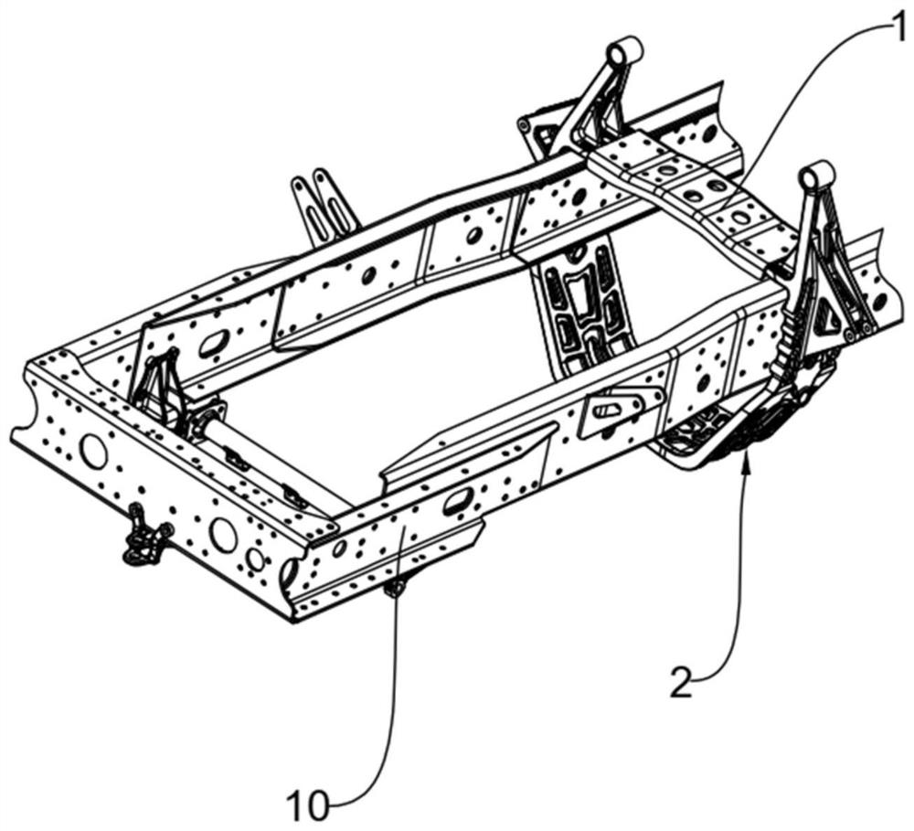
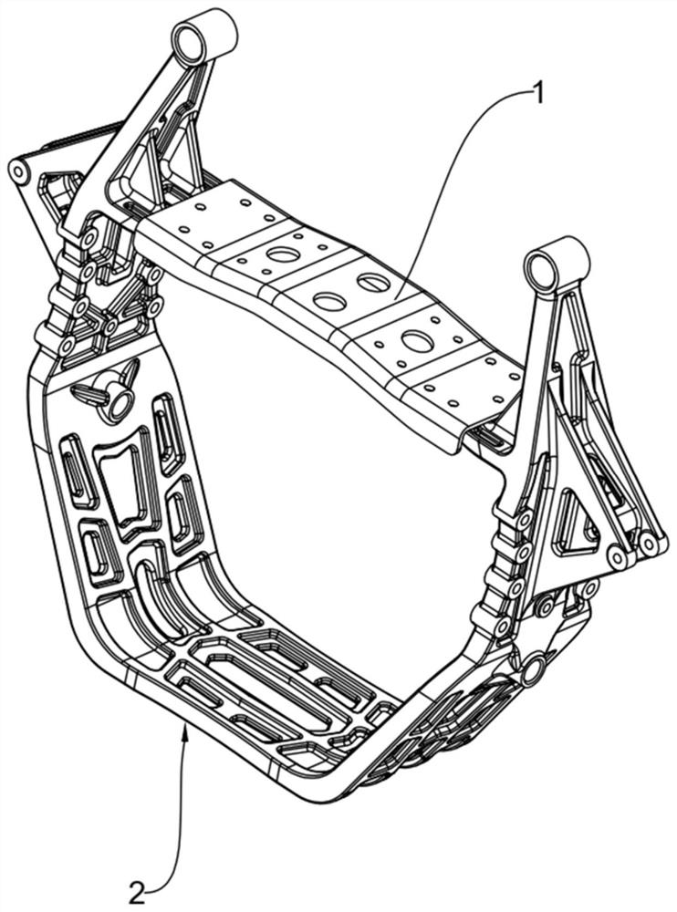
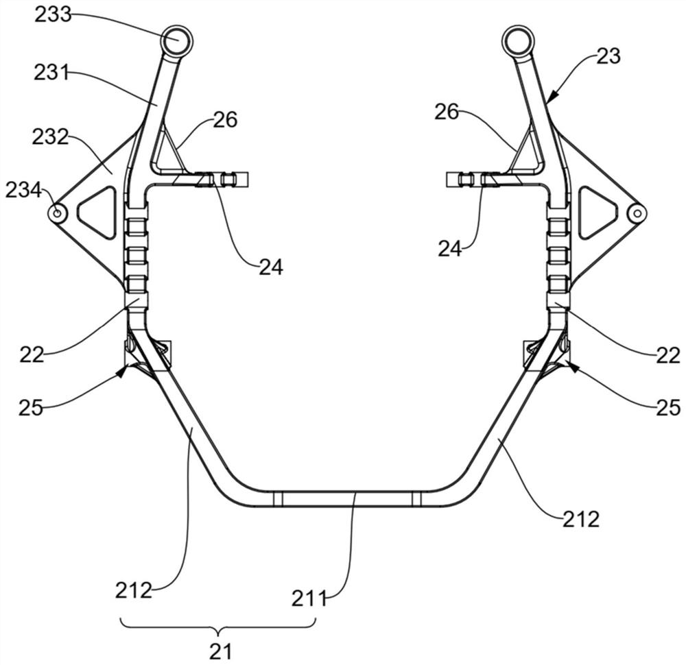
A beam assembly

A beam assembly and beam technology, applied in the field of auto parts, can solve the problems of high cost of large stamping dies, difficulty in ensuring the accuracy of the outer width of the frame due to production dimensional errors, and complex shapes of the beams of the front springs and rear brackets. The effect of stability, improving product dimensional accuracy, and reducing the number of parts

Active Publication Date: 2022-03-22
FAW JIEFANG AUTOMOTIVE CO
View PDF13 Cites 0 Cited by
  • Summary
  • Abstract
  • Description
  • Claims
  • Application Information

AI Technical Summary

Problems solved by technology

The chassis of the whole vehicle includes leaf spring rings, cab rear mounts, front spring rear bracket beams and suspension beams, and the leaf spring rings, cab rear mounts, front spring rear bracket beams and suspension beams are respectively connected to the vehicle frame and They are all concentrated in the middle and front end of the vehicle, which makes the layout space of the vehicle very limited and brings great trouble to the layout of the vehicle.
In addition, the crossbeam of the front spring and rear bracket mostly adopts sheet metal stamping structure. Due to the influence of the position of the gearbox, the shape of the crossbeam of the front spring and rear bracket is mostly complicated, resulting in high cost of large stamping dies and low torsional stiffness of the front spring and rear bracket beam.
At the same time, due to the production size error of the complex sheet metal structure, it is difficult to guarantee the accuracy of the outer width of the frame at the front end

Method used


Image

  • A beam assembly
  • A beam assembly
  • A beam assembly

Examples


Embodiment Construction

[0045] The technical solutions of the present invention will be further described below in conjunction with the accompanying drawings and through specific implementation methods. It should be understood that the specific embodiments described here are only used to explain the present invention, but not to limit the present invention. In addition, it should be noted that, for the convenience of description, only the parts related to the present invention are shown in the drawings but not all of them.

[0046] Some orientation words are limited in the present invention, and under the situation of not making contrary description, the orientation words used are as " upper ", " lower ", " left ", " right ", " inner ", " outer " these orientation words It is adopted for easy understanding, and thus does not constitute a limitation to the protection scope of the present invention.

[0047] In the present invention, unless otherwise clearly specified and limited, a first feature bein...


PUM


Abstract

The invention relates to the technical field of automobile parts, and specifically discloses a beam assembly. The beam assembly includes: a suspension beam; a front spring and a rear support beam assembly are integrally formed by casting. The front spring and rear support beam assembly includes: a front spring The rear support beam, the front spring and the rear support beam include a bottom plate and a side plate, and the opposite ends of the bottom plate are connected with side plates; the frame fixing part is used for connecting with the frame, and the two side plates are connected with the frame fixing part ;The rear suspension bracket of the cab is used to connect the rear suspension of the cab, and the two frame fixing parts are connected with the rear suspension bracket of the cab; the suspension beam bracket is used to connect the suspension beam, the rear of the two cabs The suspension brackets are all connected with suspension beam brackets, the suspension beam, the frame fixing part and the front spring rear bracket beam form a ring structure; the leaf spring lifting ring bracket is used to connect the leaf spring lifting ring, and both side plates are provided with plates Spring Ring Bracket. The torsional rigidity of the beam assembly is high, the outer width is high precision, the production cost is low, and the layout of the chassis is optimized.

Description

technical field [0001] The invention relates to the technical field of automobile parts, in particular to a beam assembly. Background technique [0002] With the development of commercial vehicle technology, the requirements for lightweight and integrated vehicle chassis are getting higher and higher. The chassis of the whole vehicle includes leaf spring rings, cab rear mounts, front spring rear bracket beams and suspension beams, and the leaf spring rings, cab rear mounts, front spring rear bracket beams and suspension beams are respectively connected to the vehicle frame and They are all concentrated in the middle and front end of the vehicle, which makes the layout space of the vehicle very limited and brings great trouble to the layout of the vehicle. In addition, the front spring and rear support beams mostly adopt sheet metal stamping structure. Due to the influence of the position of the gearbox, the shape of the front spring and rear support beams is mostly complica...

Claims


Application Information

Patent Timeline
Patent Type & Authority Patents(China)
IPC IPC(8): B62D21/11
CPCB62D21/11
Inventor 单连旭王继瑶李建华于宁刘嘉南赵明
Owner FAW JIEFANG AUTOMOTIVE CO
Why Eureka
Try Eureka