Bionic jumping leg adopting pneumatic series elastic joints
A series of elastic and joint technology, applied in the field of bionic robots, can solve the problems of difficult to obtain jumping performance, lack of ground energy storage structure, high peak power, etc., to achieve excellent jumping performance, achieve lightweight, and avoid weakening effects.
- Summary
- Abstract
- Description
- Claims
- Application Information
AI Technical Summary
Problems solved by technology
Method used
Image
Examples
Embodiment 1
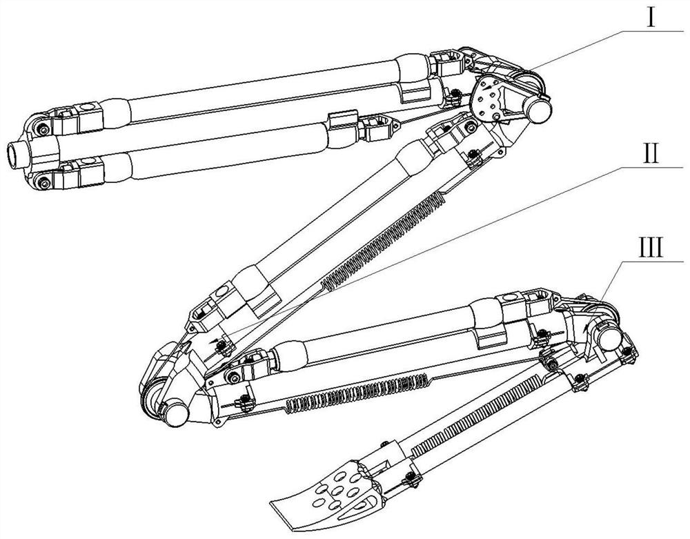
[0036] see Figure 1 to Figure 6 , a bionic jumping leg using pneumatic series elastic joints, composed of hip joint module I, knee joint module II, pneumatic series elastic ankle joint module III, characterized in that: the hip joint module I, knee joint module II, pneumatic The series elastic ankle joint module III is articulated sequentially from top to bottom, in which there are 4 pneumatic artificial muscles 11, 17, 36, 66 or 52 to drive 3 joints to rotate, and angular displacement sensors are installed at the 3 active joints respectively.
[0037]This embodiment adopts the bionic jumping leg with pneumatic series elastic joints, which has the advantages of compact structure, impact resistance, elastic energy storage, light weight and miniaturization.
Embodiment 2
[0039] This embodiment is basically the same as Embodiment 1, and the special features are as follows:
[0040] The pneumatic series elastic ankle joint module III includes tibial lower bracket 56, metatarsal upper bracket 58, foot end bracket 63, ankle joint pneumatic artificial muscle 66, ankle joint spring 60, ankle joint return spring 64, ankle joint pulley 54, ankle joint Angular displacement sensor 57, ankle joint pulley angular displacement sensor 70 and bionic jumping leg calf carbon tube 67, ankle joint pneumatic artificial muscle 66 bypasses ankle joint pulley 54 through steel wire rope 53 and connects ankle joint spring 60 to form a series elastic driver to drive the ankle Joint stretching exercise; the sole of the foot includes a foot end support 63, a support on the metatarsal bone 58, and two sole carbon tubes 61, 62, and the two sole carbon tubes 61, 62 are arranged in parallel to form the sole of the sole, and an ankle joint spring 60 is equipped on one side of ...
Embodiment 3
[0045] Such as figure 1 As shown, a bionic jumping leg using pneumatic series elastic joints, including hip joint module I, knee joint module II, pneumatic series elastic ankle joint module III; hip joint module I, knee joint module II, pneumatic series elastic ankle joint module III is articulated sequentially from top to bottom; the rotation axes of the hip joint, knee joint, and ankle joint are parallel to each other; the bone structure of the bionic jumping leg is fixed by lightweight hollow rods and resin brackets, ensuring structural strength while , to make the bionic jumping leg lightweight and miniaturized, the resin bracket is connected with an axial slot, and is connected with a bolt to form an interference fit with the lightweight hollow rod of the bone, and the hip joint, knee joint, and ankle joint are in the The minimum limit structure is provided at the resin support structure.
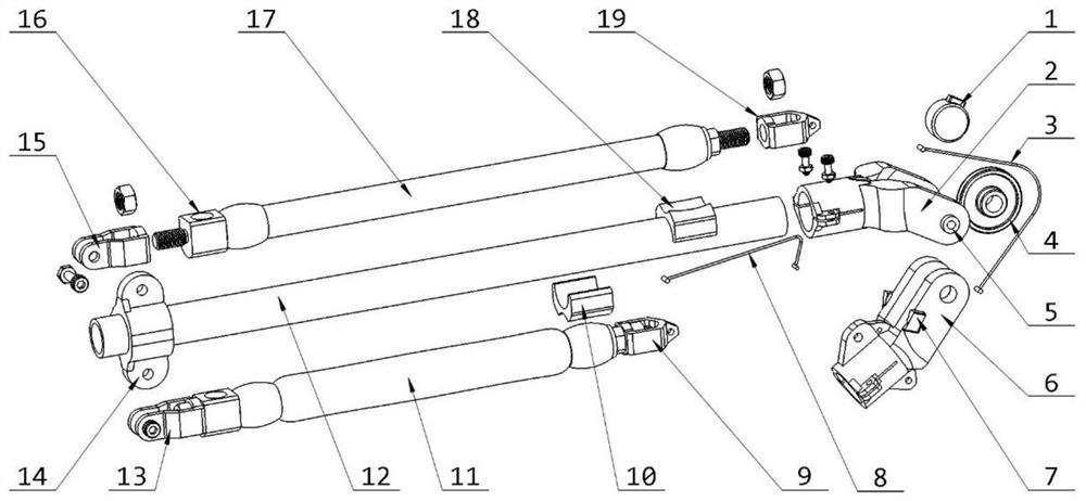
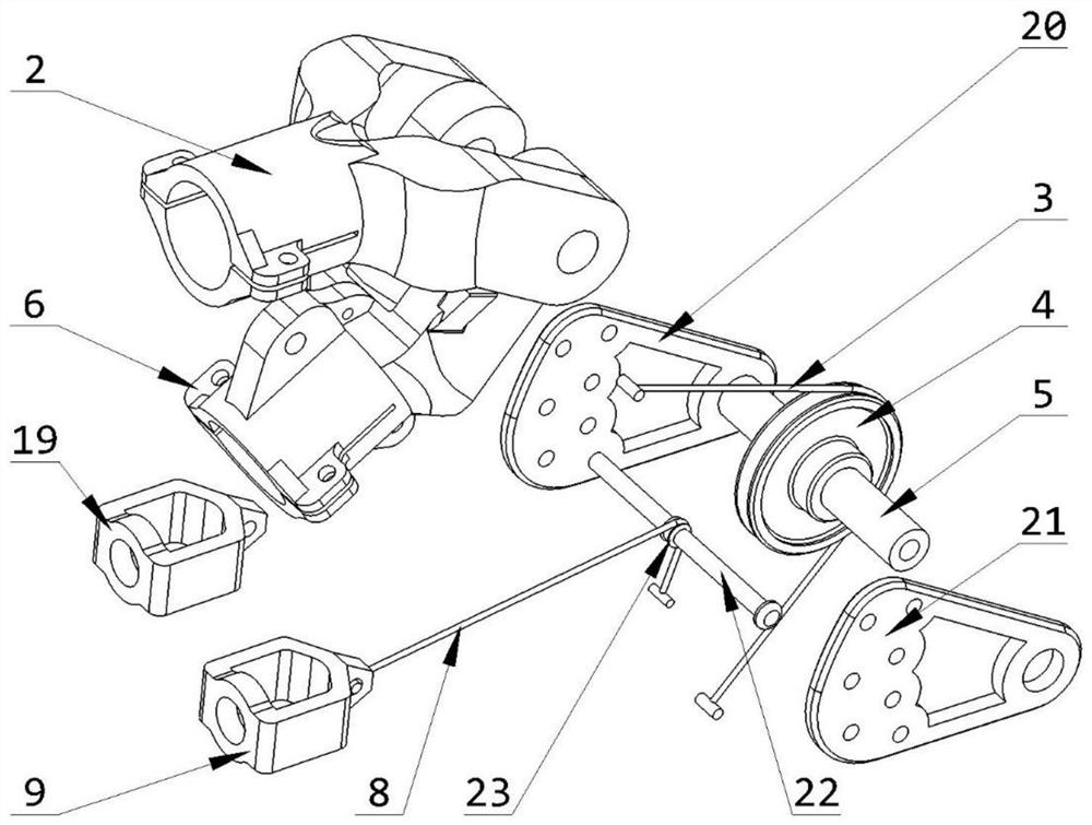
[0046] Such as figure 2 Shown, described hip joint module 1 is made of support ...
PUM
 Abstract
Description
Claims
Application Information
 - R&D
- Intellectual Property
- Life Sciences
- Materials
- Tech Scout
- Unparalleled Data Quality
- Higher Quality Content
- 60% Fewer Hallucinations
Browse by: Latest US Patents, China's latest patents, Technical Efficacy Thesaurus, Application Domain, Technology Topic, Popular Technical Reports.
© 2025 PatSnap. All rights reserved.Legal|Privacy policy|Modern Slavery Act Transparency Statement|Sitemap|About US| Contact US: help@patsnap.com


