Supercharge Your Innovation With Domain-Expert AI Agents!

Grease injection head horn mouth oil scraping device

A technology of oil scraping device and bell mouth, which is applied in the field of grease scraping head bell mouth oil scraping device, can solve the problems that cannot meet the requirements of efficiency and environmental protection, is not easy to disassemble and replace quickly, and the single guiding function of the bell mouth, etc., to achieve convenient scraping Oil packing 7. Excellent scraping effect, easy to disassemble and replace

Pending Publication Date: 2021-04-02
BAOJI JINHUI OILFIELD MACHINERY +1
View PDF2 Cites 0 Cited by
  • Summary
  • Abstract
  • Description
  • Claims
  • Application Information

AI Technical Summary

Problems solved by technology

[0002] The traditional bell mouth has a guiding function, but as the requirements for work efficiency become higher and higher, the single guiding function of the bell mouth can no longer meet the requirements of efficiency and environmental protection
[0003] The announcement number is CN208564508U, which discloses an online oil well head cleaning device for oil well minor repair operations; and the oil scraping plate and oil scraping device with announcement number CN210483646U. The common problems are that the structure is scattered, and the number of parts is too large, which is not conducive to miniaturization design. , and the assembly is complicated; especially after the wearing parts are damaged, it is not easy to quickly disassemble and replace

Method used


Image

  • Grease injection head horn mouth oil scraping device
  • Grease injection head horn mouth oil scraping device
  • Grease injection head horn mouth oil scraping device

Examples


Embodiment Construction

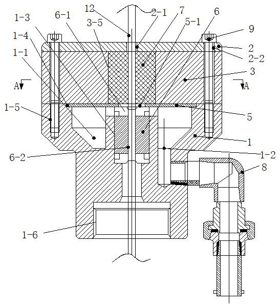
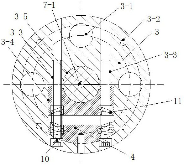
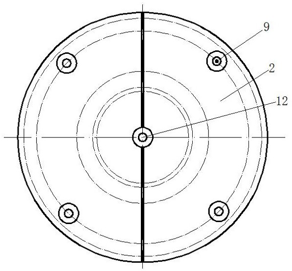
[0029] Attached below Figure 1-5 Specific examples of the present invention are described.

[0030] The following examples facilitate a better understanding of the present invention, but do not limit the present invention. The following embodiments are only some of the embodiments of the present invention, but not all of them. The components used in the following examples are commercially available unless otherwise specified.

[0031] In the present invention, unless otherwise clearly specified and limited, in the absence of a contrary statement, "upper, lower, left, right, inner, outer, top, bottom, vertical, horizontal" etc. are included in the terms The orientation words only represent the orientation of the term in the normal use state, or for the convenience of describing the present invention and simplifying the description, or the common name understood by those skilled in the art, unless otherwise clearly specified and limited, it should not be regarded as Technica...


PUM


Abstract

The invention provides a grease injection head horn mouth oil scraping device. The grease injection head horn mouth oil scraping device comprises a support; a pressing block is arranged in the centerof the support; the center of the pressing block centralizes a cable and scrapes grease; a support inner cavity is formed in the upper end of the support; an oil discharge hole is formed in the bottomend of one side of the support inner cavity; a lower pressing plate is mounted at an opening in the upper end of the support; a through hole II is formed in the center of the lower pressing plate; amiddle pressing plate is arranged at the upper end of the lower pressing plate; an oil scraping packing of a C-shaped structure is mounted in the center of the middle pressing plate; an upper pressingplate is arranged at the top end of the middle pressing plate; the upper pressing plate, the middle pressing plate, the lower pressing plate and the support are fastened and connected into a whole through vertical bolts; middle embedded blocks are mounted in notches formed in the middle pressing plate; compression springs are mounted between two sets of middle embedded blocks through horizontal bolts; the middle embedded blocks and a middle pressing block are elastically connected into a whole through horizontal bolts; and meanwhile the middle embedded blocks extrude and push the oil scrapingpacking to scrape off the grease on the cable. The device is simple and compact in structure, safe, reliable, convenient and fast to assemble, convenient to disassemble and replace, economical, energy-saving, environment-friendly, more user-friendly and more efficient in scraping.

Description

technical field [0001] The invention belongs to the technical field of oilfield wellhead equipment, and in particular relates to a bell mouth oil scraping device of a grease injection head. Background technique [0002] The traditional bell mouth has a guiding function, but as the requirements for work efficiency become higher and higher, the single guiding function of the bell mouth can no longer meet the requirements of efficiency and environmental protection. [0003] The announcement number is CN208564508U, which discloses an online oil well head cleaning device for oil well minor repair operations; and the oil scraping plate and oil scraping device with announcement number CN210483646U. The common problems are that the structure is scattered, and the number of parts is too large, which is not conducive to miniaturization design. , and the assembly is complicated; especially after the wearing parts are damaged, it is not easy to quickly disassemble and replace them. Wit...

Claims


Application Information

Patent Timeline
Patent Type & Authority Applications(China)
IPC IPC(8): E21B37/02
CPCE21B37/02
Inventor 杨万里李晴晴李英新程晓刚
Owner BAOJI JINHUI OILFIELD MACHINERY
Features
  • R&D
  • Intellectual Property
  • Life Sciences
  • Materials
  • Tech Scout
  • Unparalleled Data Quality
  • Higher Quality Content
  • 60% Fewer Hallucinations
Learn More