
Full-section shoveling and recycling device for digging, supporting and anchoring combined unit and using method

A combined unit and recovery device technology, applied in mining equipment, transportation and packaging, ground mining, etc., can solve the problem of not being able to adapt well to the turning conditions of the combination unit of excavation, support and anchor, and to the change of roadway width. Due to the problems of poor flexibility of the excavating, supporting and anchoring unit, it can achieve the effect of changing the width of the roadway, easily adapting to the working conditions of up and down slopes, and improving the flexibility.

Pending Publication Date: 2021-04-02
LIAONING TECHNICAL UNIVERSITY
View PDF0 Cites 4 Cited by
  • Summary
  • Abstract
  • Description
  • Claims
  • Application Information

AI Technical Summary

Problems solved by technology

Taking the shoveling unit of the digging, supporting and anchoring unit as an example, the traditional shoveling unit has a poor recovery ability for coal falling on both sides of the roadway, and cannot adapt well to changes in the width of the roadway. The ability is also weak, and it cannot be well adapted to the turning conditions of the DSA unit, resulting in poor flexibility of the DSA unit

Method used


Image

  • Full-section shoveling and recycling device for digging, supporting and anchoring combined unit and using method
  • Full-section shoveling and recycling device for digging, supporting and anchoring combined unit and using method
  • Full-section shoveling and recycling device for digging, supporting and anchoring combined unit and using method

Examples


Embodiment Construction

[0022] The present invention will be further described in detail below in conjunction with the accompanying drawings and specific embodiments.

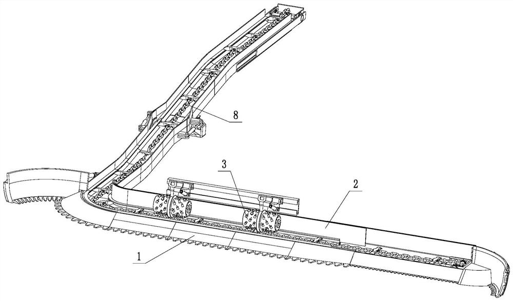
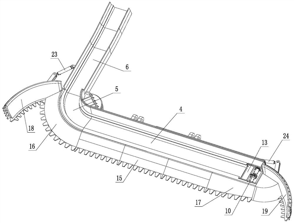
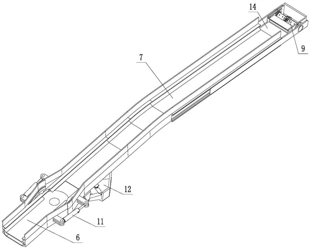
[0023] like Figure 1~5 As shown in the figure, a full-section shoveling and recovery device for a digging, supporting and anchoring combined unit includes a scraping mechanism 1, a transportation mechanism 2 and an auxiliary crushing mechanism 3; the transportation mechanism 2 adopts a right-angle turn structure, and one branch of the transportation mechanism 2 The arm is located at the front end of the excavation, support and anchor unit, and the other arm of the transport mechanism 2 is located at the side of the excavation, support and anchor unit; The front end of the transport mechanism 2; the auxiliary crushing mechanism 3 is located above the shovel mechanism 1, and the auxiliary crushing mechanism 3 is arranged at the front end of the excavation, support and anchor unit.

[0024] Described transport mechanism 2 comprises tra...


PUM


Abstract

The invention discloses a full-section shoveling and recycling device for a digging, supporting and anchoring combined unit and a using method. The full-section shoveling and recycling device comprises a shoveling plate mechanism, a conveying mechanism and an auxiliary crushing mechanism; the conveying mechanism is of a right-angle turning type structure, one supporting arm of the conveying mechanism is located at the front end of the digging, supporting and anchoring combined unit, and the other supporting arm is located on the side of the digging, supporting and anchoring combined unit; theshoveling plate mechanism is located in front of the digging, supporting and anchoring combined unit and arranged at the front end of the conveying mechanism; and the auxiliary crushing mechanism is located above the shoveling plate mechanism and arranged at the front end of the digging, supporting and anchoring combined unit. The using method comprises the steps that falling coal on the two sidesof a roadway is pushed to the shoveling plate mechanism through inward overturning of an auxiliary shovel plate, and the falling coal enters the conveying mechanism through the shoveling plate mechanism to be conveyed outwards; the extension amount of transverse telescopic end grooves is adjusted to adapt to the width of the roadway, and the extension amount of longitudinal telescopic end groovesis synchronously adjusted to maintain the tensioning state of a scraper chain; the pitching angle of an adjustable shovel plate head is adjusted to adapt to the gradient; the turning radius of the equipment is reduced by adjusting the swing angle of tail swing type conveying grooves to adapt to the turning working condition; and the size of coal briquettes is reduced through a crushing roller.

Description

technical field [0001] The invention belongs to the technical field of coal mining machinery, and in particular relates to a full-section shoveling recovery device and a use method for a digging, supporting and anchoring combined unit. Background technique [0002] As a typical fully mechanized mining equipment, the excavation, support and anchor unit has been proved to have good performance in downhole operation, but the performance of individual functional modules still needs to be improved. Taking the shoveling unit of the digging, supporting and anchoring unit as an example, the traditional shoveling unit has a poor recovery ability for coal falling on both sides of the roadway, and cannot adapt well to changes in the width of the roadway. The ability is also weak, and it cannot be well adapted to the turning conditions of the DSA unit, resulting in poor flexibility of the DSA unit. Contents of the invention [0003] Aiming at the problems existing in the prior art, t...

Claims


Application Information

Patent Timeline
IPC IPC(8): E21F13/06E21F17/00E21C41/18E21F13/00
CPCE21C41/18E21F13/002E21F13/06E21F17/00
Inventor 谢苗董钰峰刘治翔卢进南毛君
Owner LIAONING TECHNICAL UNIVERSITY
Learn More