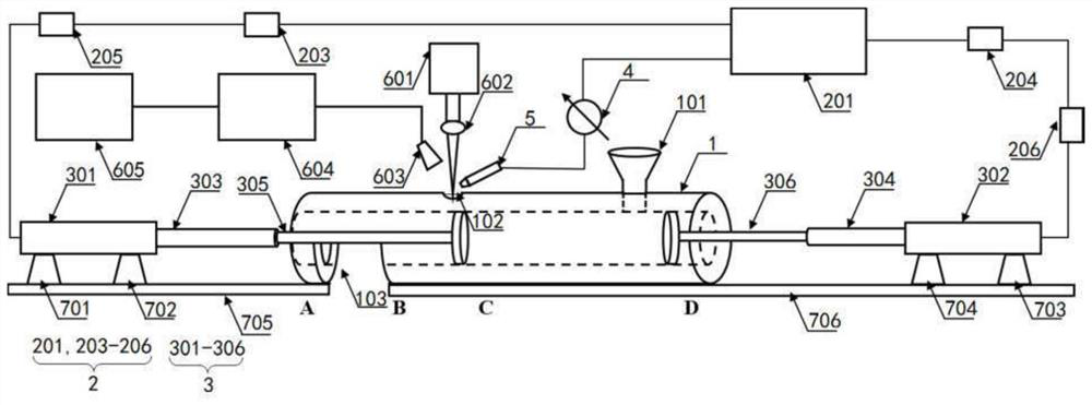
An online powder detection device based on laser-induced breakdown spectroscopy
A technology of laser-induced breakdown and detection device, applied in the field of atomic emission spectrometry detection, can solve the problems of online real-time detection of unfavorable powder samples, the overall structure of the detection system is complex, and the volume is large, so as to improve detection accuracy, wide application range, The effect of the simple structure of the device
- Summary
- Abstract
- Description
- Claims
- Application Information
AI Technical Summary
Problems solved by technology
Method used
Image
Examples
Embodiment 1
[0031] In this embodiment, the power control unit 2 includes an air compressor 201 and two control branches connected to the air compressor 201 . Specifically, seefigure 1 , one of the control branches includes a first solenoid valve 203 and a first speed regulating valve 205, the input end of the first solenoid valve 203 is connected to the first air flow branch of the air compressor 201, and the output end of the first solenoid valve 203 is connected to the first The input end of a speed regulating valve 205 . Another control branch includes a second solenoid valve 204 and a second speed regulating valve 206, the input end of the second solenoid valve 204 is connected to the second air flow branch of the air compressor 201, and the output end of the second solenoid valve 204 is connected to the second The input end of the speed control valve 206.
[0032] The air compressor 201 is the driving source of the powder sample processing module, which can provide a maximum pressur...
Embodiment 2
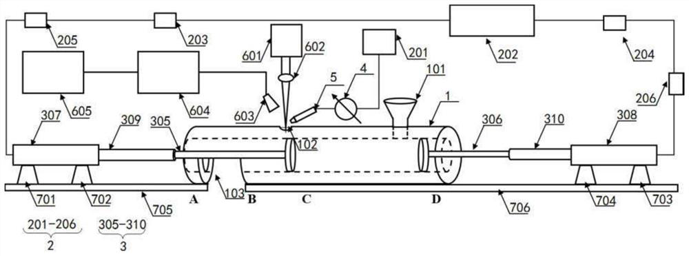
[0050] In this embodiment, the power control unit 2 includes an air compressor 201, a hydraulic pump 202, and two control branches connected to the hydraulic pump 202. The structure of the control branch is the same as that of the control branch in Embodiment 1. Let me repeat. The two pushing sub-units both include a hydraulic cylinder, an inner rod of the hydraulic cylinder and a push rod. One end of the push rod is connected to the inner rod of the hydraulic cylinder, and the other end of the push rod is inserted into the constrained metal long pipe 1. The hydraulic cylinder and the control branch are one by one Corresponding connectivity, such as figure 2 shown. The two hydraulic branches generated by the hydraulic pump 202 are respectively adjusted in speed and direction by the two control branches, and then enter the hydraulic cylinders connected to each control branch to push the inner rod and push rod of the hydraulic cylinder relative to the restrained metal long pip...
Embodiment 3
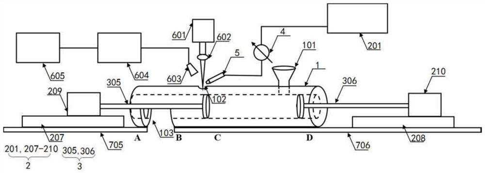
[0053] In this embodiment, the power control unit 2 includes an air compressor 201, two guide rails located at both ends of the constraining long metal tube 1, and servo motors arranged on each guide rail, and the servo motors can move on the guide rails. Both of the above two pushing subunits include push rods, and the servo motors are connected to the push rods in one-to-one correspondence, such as image 3 As shown, to drive the push rod to move relative to the constrained metal long pipe 1.
[0054] In this embodiment, the driving source in the power control unit 2 is replaced by the first guide rail 207, the second guide rail 208, the first servo motor 209, and the second servo motor 210; putter. The drive source and drive device can provide faster movement speed and higher control precision, and the device as a whole is simpler and easier to automate, and is suitable for scenarios that require high detection speed and the sample itself is easy to form. Other structures...
PUM
 Abstract
Description
Claims
Application Information
 - R&D
- Intellectual Property
- Life Sciences
- Materials
- Tech Scout
- Unparalleled Data Quality
- Higher Quality Content
- 60% Fewer Hallucinations
Browse by: Latest US Patents, China's latest patents, Technical Efficacy Thesaurus, Application Domain, Technology Topic, Popular Technical Reports.
© 2025 PatSnap. All rights reserved.Legal|Privacy policy|Modern Slavery Act Transparency Statement|Sitemap|About US| Contact US: help@patsnap.com


