Broadband high-sensitivity resonant piezoelectric MEMS microphone

A high-sensitivity, resonant technology, applied in piezoelectric/electrostrictive transducer microphones, planar diaphragms, electrical components, etc., can solve problems such as low sensitivity and achieve high-sensitivity effects

Active Publication Date: 2021-04-02
武汉敏声新技术有限公司
View PDF11 Cites 5 Cited by
  • Summary
  • Abstract
  • Description
  • Claims
  • Application Information

AI Technical Summary

Problems solved by technology

However, the traditional piezoelectric MEMS microphone has only one resonant frequency, and the sensitivity is the highest at the resonant frequency. For the microphone whose resonant frequency is much higher than 20kHz, the sensitivity in the range of 20Hz to 20kHz is low

Method used


Image

  • Broadband high-sensitivity resonant piezoelectric MEMS microphone
  • Broadband high-sensitivity resonant piezoelectric MEMS microphone
  • Broadband high-sensitivity resonant piezoelectric MEMS microphone

Examples


Embodiment 1

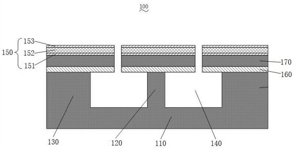
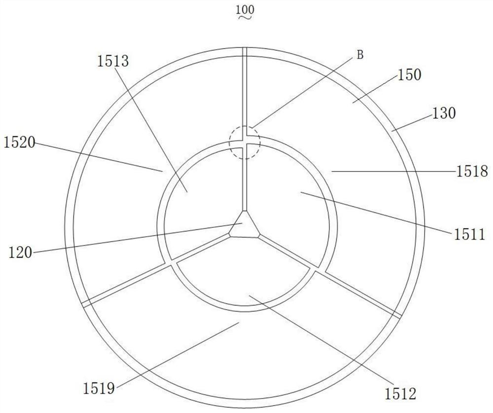
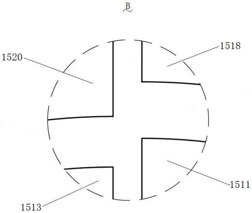
[0042] Embodiment one, with reference to figure 2 with image 3 As shown, the outer peripheral support part 130 has a ring-shaped structure, and three fan-shaped diaphragms 150 of different sizes are installed on the central support part 120, which are the first central diaphragm 1511, the second central diaphragm 1512 and the second central diaphragm 150 respectively. Three central diaphragms 1513, three fan-shaped diaphragms 150 of different sizes are installed on the peripheral support part 130, which are respectively the first peripheral diaphragm 1518, the second peripheral diaphragm 1519 and the third peripheral diaphragm 1520, one The central diaphragm, the second central diaphragm 1512 and the third central diaphragm 1513 present a stepped arrangement, the first peripheral diaphragm 1518, the second peripheral diaphragm 1519 and the third peripheral diaphragm 1520 present a stepped arrangement, the second The first central diaphragm 1511 , the second central diaphrag...

Embodiment 2

[0045] Embodiment two, refer to Figure 4 As shown, the outer peripheral support part 130 is a square ring structure, and four trapezoidal diaphragms 150 of the same size are installed on the central support part 120, which are respectively the fourth central diaphragm 1514, the fifth central diaphragm 1515, and the sixth diaphragm 150. The central diaphragm 1516 and the seventh central diaphragm 1517, four trapezoidal diaphragms 150 of the same size are installed on the peripheral support part 130, which are respectively the fourth peripheral diaphragm 1521, the fifth peripheral diaphragm 1522, and the sixth peripheral diaphragm. diaphragm 1523 and a seventh peripheral diaphragm 1524 . The fourth central diaphragm 1514, the fifth central diaphragm 1515, the sixth central diaphragm 1516 and the seventh central diaphragm 1517 have the same shape and size, the fourth peripheral diaphragm 1521, the fifth peripheral diaphragm 1522, the sixth peripheral diaphragm The diaphragm 152...


PUM


Abstract

The invention discloses a broadband high-sensitivity resonant piezoelectric MEMS microphone, and the microphone comprises a substrate and a piezoelectric diaphragm; the top of the substrate is provided with a central support part and a peripheral support part, and a back cavity is arranged between the central support part and the peripheral support part, so that a central vibration area and a peripheral vibration area are formed between the central support part and the peripheral support part; the piezoelectric vibrating diaphragm is suspended on the back cavity, the piezoelectric vibrating diaphragm comprises a plurality of diaphragms, the central vibrating area is provided with at least one diaphragm mounted on the central supporting part, the peripheral vibrating area is provided with at least one diaphragm mounted on the peripheral supporting part, the plurality of diaphragms are different in one or more of shape, size or thickness, and a gap is formed between every two adjacent diaphragms; the resonant frequencies of the diaphragms are different, so the sensitivity curve of the microphone can generate a section of flat broadband between the minimum resonant frequency and the maximum resonant frequency of the piezoelectric diaphragm, and the sensitivity curve of the microphone has higher sensitivity in the frequency band range.

Description

technical field [0001] The invention relates to the technical field of MEMS piezoelectric devices, in particular to a broadband high-sensitivity resonant piezoelectric MEMS microphone. Background technique [0002] A microphone is an energy conversion device that converts sound signals into electrical signals in different ways. Piezoelectric MEMS microphones are energy conversion devices that convert acoustic signals into electrical signals by using the piezoelectric effect. In recent years, piezoelectric MEMS microphones have small size, stable performance, high signal-to-noise ratio, good sensitivity and fast response. Such microphones have been widely used in smart wearable devices and smartphones. [0003] The frequency range of human perception of sound is 20Hz to 20kHz, so the working frequency range of the designed piezoelectric MEMS microphone should be around the frequency band of 20Hz to 20kHz, and the sensitivity curve in the working frequency range is required t...

Claims


Application Information

Patent Timeline
Patent Type & Authority Applications(China)
IPC IPC(8): H04R19/04H04R17/02H04R23/02H04R7/04
CPCH04R7/04H04R17/02H04R19/04H04R23/02H04R2201/003
Inventor 孙成亮杨超翔林炳辉胡博豪温志伟曲远航王雅馨
Owner 武汉敏声新技术有限公司
Why Eureka
Try Eureka