Batch industrial mold coloring equipment
A chemical industry and mold technology, applied in the field of batch industrial mold coloring equipment, can solve the problems of waste of raw materials, heavy workload, etc.
- Summary
- Abstract
- Description
- Claims
- Application Information
AI Technical Summary
Problems solved by technology
Method used
Image

Examples
Embodiment 1
[0059] A batch of industrial mold coloring equipment, such as figure 1 As shown, it includes a base 1 , a feeding mechanism 2 and a transmission mechanism 3 , the top left side of the base 1 is connected with the feeding mechanism 2 , and the top rear side of the base 1 is connected with the transmission mechanism 3 .
[0060] The staff can place the mold on the loading mechanism 2, and then start the loading mechanism 2 to drive the transmission mechanism 3 to work. The loading mechanism 2 works to automatically load the mold, and then the transmission mechanism 3 works to transfer the mold to the designated position. Coloring, after the coloring is completed, the mold can be collected after it is air-dried, and the feeding mechanism 2 can be stopped after use.
Embodiment 2
[0062] On the basis of Example 1, such as figure 2 , image 3 , Figure 4 and Figure 5 As shown, the feeding mechanism 2 includes a support column 21, a biaxial motor 22, a half spur gear 23, a carriage 24, a rotating shaft 25, a first transmission group 26, a first spur gear 27, a second transmission group 28, and a push frame 29. The first spring 210, the storage basket 211, the second spring 212 and the push plate 213, the front side of the top of the base 1 is connected with a support column 21, the top of the support column 21 is provided with a biaxial motor 22, and the left side of the biaxial motor 22 The output shaft is connected with a semi-spur gear 23, and the left side of the top of the base 1 is symmetrically provided with a carriage 24, and the top of the carriage 24 is rotatably connected with 2 rotating shafts 25, and the right side of the carriage 24 on the right side is rotationally connected with a second shaft. Straight gear 27, the first transmission g...
Embodiment 3
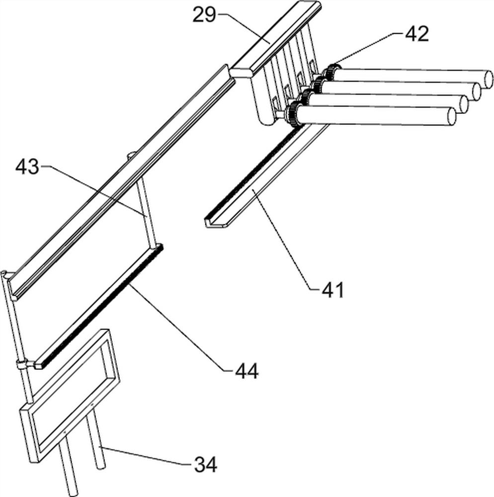
[0066] On the basis of Example 2, such as Figure 6 , Figure 7 , Figure 8 , Figure 9 and Figure 10 As shown, it also includes a rotation mechanism 4, the rotation mechanism 4 includes a first rack 41, a second spur gear 42, a support rod 43 and a second rack 44, and the middle part of the front side of the second support frame 35 is provided with a first tooth Bar 41, a plurality of second spur gears 42 are connected to the rear portion of the push frame 29, and the second spur gear 42 meshes with the first rack 41, and the middle part of the front side of the connecting rod 38 is connected with a support rod 43, and the bottom of the support rod 43 is connected to the first gear rack. A second rack 44 is connected between the supporting frames 34 , and the second rack 44 meshes with the second spur gear 42 .
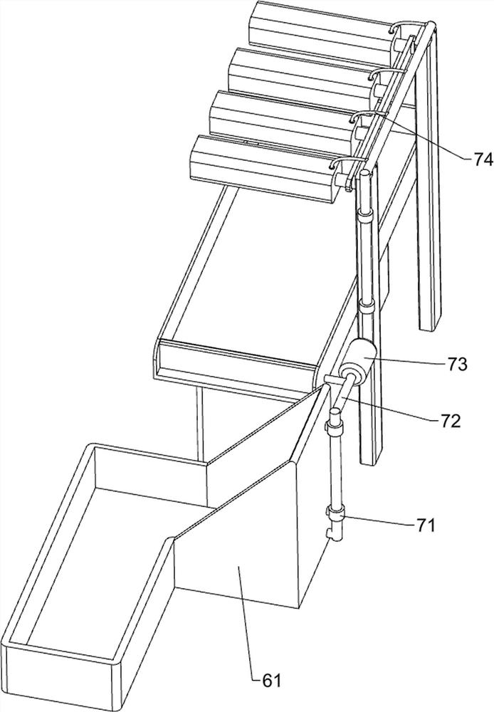
[0067] Also include a coloring mechanism 5, the coloring mechanism 5 includes a first water tank 51, a hairbrush 52, a fixed plate 53, a paint box 54, a fixed b...
PUM
 Abstract
Description
Claims
Application Information
 - R&D
- Intellectual Property
- Life Sciences
- Materials
- Tech Scout
- Unparalleled Data Quality
- Higher Quality Content
- 60% Fewer Hallucinations
Browse by: Latest US Patents, China's latest patents, Technical Efficacy Thesaurus, Application Domain, Technology Topic, Popular Technical Reports.
© 2025 PatSnap. All rights reserved.Legal|Privacy policy|Modern Slavery Act Transparency Statement|Sitemap|About US| Contact US: help@patsnap.com