Milling cutter tool setting mechanism, milling machine and milling cutter tool setting control method

A control method and technology of milling cutters, which are applied in the direction of automatic control devices, manufacturing tools, metal processing machinery parts, etc., can solve the problem of low precision of milling cutter setting, and achieve the effect of improving the depth precision of milling slots

Pending Publication Date: 2021-04-06
SHENZHEN YUANMINGJIE TECH
View PDF0 Cites 3 Cited by
  • Summary
  • Abstract
  • Description
  • Claims
  • Application Information

AI Technical Summary

Problems solved by technology

[0004] The main purpose of the present invention is to provide a milling cutter tool setting mechanism, a milling machine and a milling cutter tool setting control method, aiming at solving the technical problem that the milling cutter tool setting accuracy is not high in the prior art

Method used


Image

  • Milling cutter tool setting mechanism, milling machine and milling cutter tool setting control method
  • Milling cutter tool setting mechanism, milling machine and milling cutter tool setting control method
  • Milling cutter tool setting mechanism, milling machine and milling cutter tool setting control method

Examples


Embodiment Construction

[0043] The following will clearly and completely describe the technical solutions in the embodiments of the present invention with reference to the accompanying drawings in the embodiments of the present invention. Obviously, the described embodiments are only part of the embodiments of the present invention, not all of them. Based on the embodiments of the present invention, all other embodiments obtained by persons of ordinary skill in the art without creative efforts fall within the protection scope of the present invention.

[0044] It should be noted that all directional indications (such as up, down, left, right, front, back...) in the embodiments of the present invention are only used to explain the relationship between the components in a certain posture (as shown in the accompanying drawings). Relative positional relationship, movement conditions, etc., if the specific posture changes, the directional indication will also change accordingly.

[0045] In the present in...


PUM


Abstract

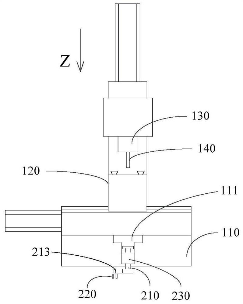
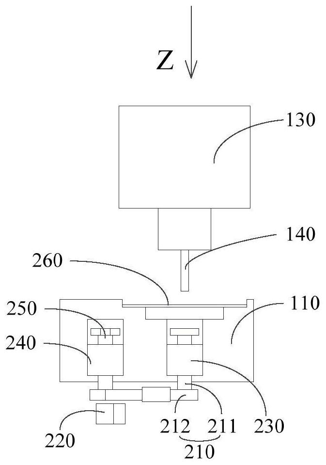
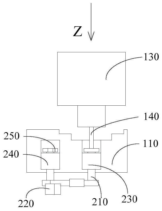
The invention discloses a milling cutter tool setting mechanism, a milling machine and a milling cutter tool setting control method. The milling cutter tool setting mechanism is arranged on a workbench of the milling machine, the workbench is provided with a workpiece mounting groove, the milling cutter tool setting mechanism comprises a moving part and an in-place sensor, wherein the moving part is arranged in the workpiece mounting groove and can move in the setting and feeding direction of the milling machine, and the tool setting and feeding direction is perpendicular to the workbench; and the in-place sensor is fixedly arranged on the workbench and is arranged on the side, deviating from a milling cutter, of a moving part, and the in-place sensor is used for sending out a tool setting completion signal when the moving part is pushed by the milling cutter to trigger the in-place sensor. According to the milling cutter tool setting device, a milling cutter mounting height parameter value with higher precision can be obtained, specifically, the milling cutter tool setting precision is higher.

Description

technical field [0001] The invention relates to the field of drilling equipment, in particular to a milling tool setting mechanism, a milling machine and a milling tool setting control method. Background technique [0002] In the machining process, it is usually necessary to replace different milling cutters to achieve cutting in different areas. After replacing the milling cutters, precise Z-axis tool setting is required to ensure that the Z-axis depth of the template after the tool change remains consistent. [0003] However, in the related art, the precision of milling cutter setting is not high. Contents of the invention [0004] The main purpose of the present invention is to provide a milling cutter setting mechanism, a milling machine and a milling cutter tool setting control method, aiming to solve the technical problem of low milling cutter tool setting accuracy in the prior art. [0005] In order to achieve the above object, a milling cutter tool setting mechani...

Claims


Application Information

Patent Timeline
Patent Type & Authority Applications(China)
IPC IPC(8): B23Q17/22B23Q15/22
CPCB23Q15/22B23Q17/22
Inventor 苏元桂陈文志单佳伟黎理杰
Owner SHENZHEN YUANMINGJIE TECH
Why Eureka
Try Eureka