Wire drawing device for carrying out various processing types on aluminum plates
A kind of wire drawing and type technology, applied in the direction of grinding drive device, metal processing equipment, grinding/polishing safety device, etc., can solve the problems that affect the effect of wire drawing processing, affect production efficiency, affect product output, etc., and achieve simple equipment structure , the effect of good market prospects
- Summary
- Abstract
- Description
- Claims
- Application Information
AI Technical Summary
Problems solved by technology
Method used
Image

Examples
Embodiment Construction
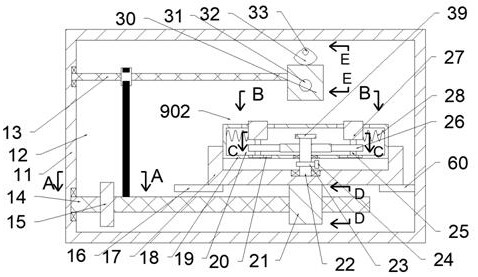
[0019] Combine below Figure 1-8 The present invention is described in detail, wherein, for the convenience of description, the orientations mentioned below are defined as follows: figure 1 The up, down, left, right, front and back directions of the projection relationship itself are the same.
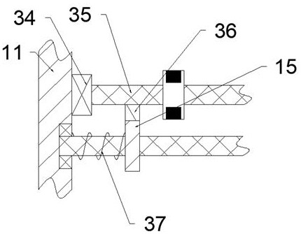
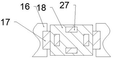
[0020] A wire drawing device for various processing types of aluminum plates according to the present invention includes a processing box 11, and the processing box 11 is provided with a processing chamber 12 with a through hole on the front inner wall. A wire drawing device 901 is provided, and a clamping device 902 is provided in the processing chamber 12. The clamping device 902 includes a clamping box 18 located in the processing chamber 12, and the clamping box 18 is provided with There is a clamping chamber 19, the lower inner wall of the clamping chamber 19 is rotated and provided with a rotating rod 22 extending into the processing chamber 12, and the lower inner wall of the c...
PUM
 Abstract
Description
Claims
Application Information