
Tire processing equipment

A processing equipment and tire technology, applied in the field of tire processing, can solve the problems of artificial bead placement, etc., and achieve the effect of protecting safety, high quality and improving quality

Inactive Publication Date: 2021-04-06
吴养社
View PDF1 Cites 0 Cited by
  • Summary
  • Abstract
  • Description
  • Claims
  • Application Information

AI Technical Summary

Problems solved by technology

[0002] For example, the publication number CN111730886A includes a horizontal bottom plate, a support frame, an inverted U-shaped fixed frame, an air rod, a horizontal connecting frame, a vertical mounting frame, a pressure wheel, a side mounting frame, a softening fan, a cooling fan, a bottom supporting buffer frame structure, and a bottom wheel. Frame, conveying roller, conveyor belt, conveying motor, adjustable positioning frame structure, drive storage frame structure and detachable winding frame structure, the support frame bolts are installed on the left and right sides of the middle and upper part of the horizontal bottom plate; the inverted U Type fixing frame bolts are installed on the top of the support frame; the air rod bolts are installed on the middle and lower part of the top of the inverted U-shaped fixing frame; the described transverse connecting frame bolts are installed on the bottom of the air rod; place bead

Method used


Image

  • Tire processing equipment
  • Tire processing equipment
  • Tire processing equipment

Examples


specific Embodiment approach 1

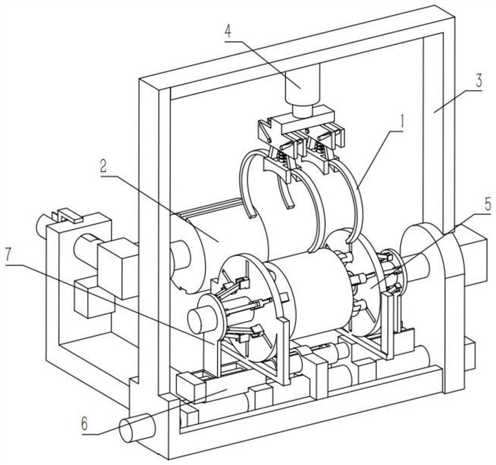
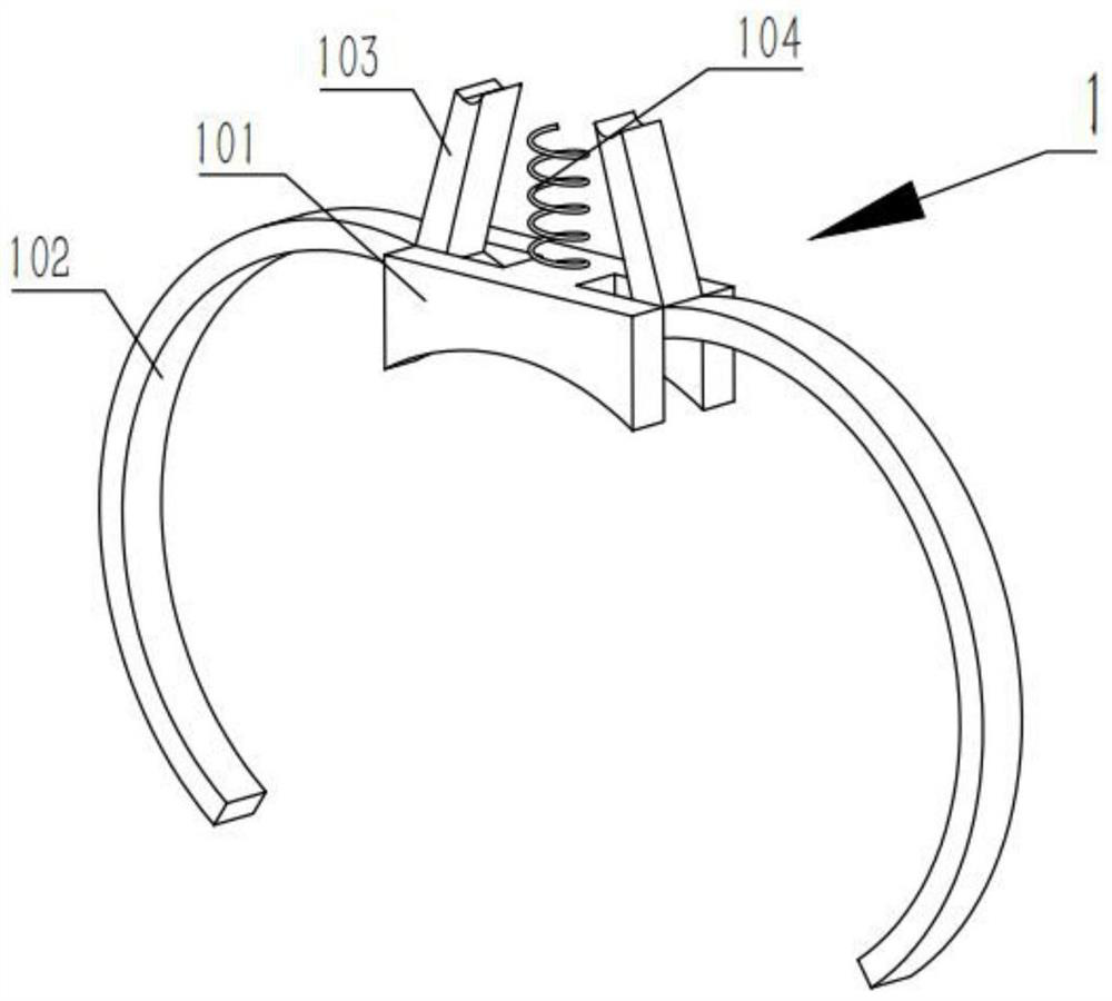
[0029] Combine below Figure 1-8 Illustrating this embodiment, a tire processing equipment includes a position limiting mechanism 1, a bead fixing mechanism 2 and a main frame mechanism 3, characterized in that the position limiting mechanism 1 includes an annular frame fixing plate 101, an annular fixing frame 102, The rotating rod 103 and the spring 104, the two annular fixing frames 102 are both rotatably connected to the annular frame fixing plate 101, the two rotating rods 103 are respectively fixedly connected to the upper ends of the two annular fixing frames 102, and the lower end of the spring 104 is fixedly connected to the annular frame. On the upper end of the frame fixing plate 101, the bead fixing mechanism 2 includes a telescopic rod 207 and a bead placer 208, and the bead placer 208 is fixedly connected to the telescopic rod 207, and the main frame mechanism 3 includes a tire building roller 304;

[0030]The placement of the bead can be completed automatically,...

specific Embodiment approach 2

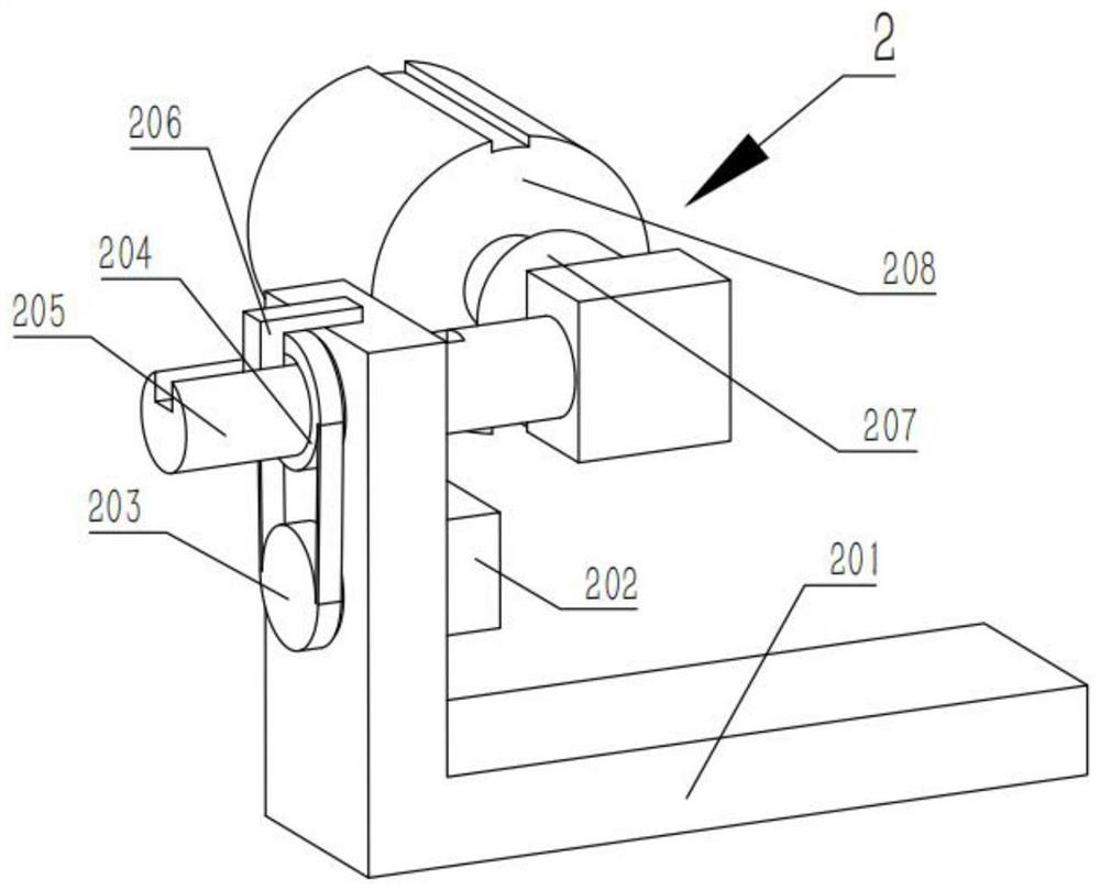
[0032] Combine below Figure 1-8 Describing this embodiment, this embodiment further describes Embodiment 1. The bead fixing mechanism 2 further includes a bead fixing frame 201, a motor 202, a pulley 203, a threaded ring 204, a threaded rod 205 and a rotation limiting rod 206. The motor 202 is fixedly connected to the bead holder 201, the pulley 203 is fixedly connected to the output shaft of the motor 202, the pulley 203 is rotatably connected to the bead holder 201, the threaded ring 204 is rotatably connected to the bead holder 201, and the threaded rod 205 and the threaded ring 204 are driven by threads, the pulley 203 and the threaded ring 204 are driven by a belt, the rotation limiting rod 206 is fixedly connected to the bead holder 201, the threaded rod 205 is provided with a chute, and the threaded rod 205 is slidably connected to the threaded rod 205. On the ring 204, the telescopic rod 207 is fixedly connected to the threaded rod 205;

[0033] The rotation of the o...

specific Embodiment approach 3

[0035] Combine below Figure 1-8 Describing this embodiment, this embodiment further describes Embodiment 2. The main body frame mechanism 3 further includes a main body support frame 301, a sliding rail 302, a rotating shaft 303 and a power motor 305. The sliding rail 302 is fixedly connected to the main body support frame At the bottom end of 301, the rotating shaft 303 is rotatably connected to the right end of the main body support frame 301, the power motor 305 is fixedly connected to the right end of the main body support frame 301, the rotating shaft 303 is fixedly connected to the output shaft of the power motor 305, and the tire building roller 304 is fixed connected to the left end of the rotating shaft 303;

[0036] The rotation of the output shaft of the power motor 305 drives the rotation of the rotation shaft 303, and the rotation of the rotation shaft 303 drives the rotation of the tire building roller 304, and the rotation of the tire building roller 304 can be...


PUM


Abstract

The invention relates to the technical field of tire processing, in particular to tire processing equipment. The equipment comprises a position limiting mechanism, a tire bead fixing mechanism and a main body frame mechanism, wherein the position limiting mechanism comprises annular frame fixing plates, annular fixing frames, rotating rods and springs, the two annular fixing frames are rotationally connected to the interiors of the annular frame fixing plates correspondingly, the two rotating rods are fixedly connected to the upper ends of the two annular fixing frames correspondingly, the lower ends of the springs are fixedly connected to the upper ends of the annular frame fixing plates, the tire bead fixing mechanism comprises a telescopic rod and a tire bead placer, the tire bead placer is fixedly connected to the telescopic rod, the main body frame mechanism comprises a tire forming roller and can automatically complete placement of a tire bead, and can limit a position of the tire bead, the tire bead can be located at the best processing position, a processed tire can be more stable and higher in quality, manual placement is not needed, it is guaranteed that the position of the tire bead is determined, deviation is avoided, and the safety of workers can be protected.

Description

technical field [0001] The invention relates to the technical field of tire processing, and more particularly relates to a tire processing equipment. Background technique [0002] For example, the publication number CN111730886A includes a horizontal base plate, a support frame, an inverted U-shaped fixing frame, a gas bar, a horizontal connecting frame, a vertical mounting frame, a pressing wheel, a side mounting frame, a softening fan, a cooling fan, a bottom supporting buffer frame structure, and a bottom wheel frame, conveying roller, conveying belt, conveying motor, adjustable positioning frame structure, drive storage frame structure and easy-to-remove winding frame structure, the support frame bolts are installed on the left and right sides of the upper middle and upper part of the horizontal base plate; the inverted U U-shaped fixing frame bolts are installed on the upper part of the support frame; the air rod bolts are installed at the middle and lower part of the t...

Claims


Application Information

Patent Timeline
Patent Type & Authority Applications(China)
IPC IPC(8): B29D30/50
CPCB29D30/50
Inventor 吴养社
Owner 吴养社
Learn More