Novel polyurethane flat steel belt winding and clamping device

A clamping device, polyurethane technology, applied in the direction of coiling strips, transportation and packaging, thin material handling, etc., can solve the problems of small clamping area, insufficient clamping force, and coiled steel belt stuck, and achieve simplification. Operation process, improve production efficiency, and ensure the effect of production rhythm

Pending Publication Date: 2021-04-06
依合斯电梯配件(上海)有限公司
View PDF0 Cites 2 Cited by
  • Summary
  • Abstract
  • Description
  • Claims
  • Application Information

AI Technical Summary

Problems solved by technology

[0003] The original winding and clamping device mainly has the following two problems: the clamping force is not enough during winding, and the clamped material head of the steel strip is easy to be pulled off during the winding process of the steel strip, which makes the coiling process unable to continue , the steel strip needs to be pulled back and rewound; due to the small clamping area, there will be potential pinch marks on the clamped steel strip head; the coiled steel strip will be stuck on the winding clamping device after coiling , which makes it difficult for the winding clamping device to come out from the core of the coiled material. It takes a lot of effort to pull out the device after it is necessary to manually pull out the device before the subsequent packaging can be carried out

Method used

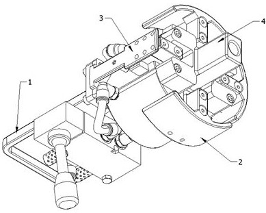
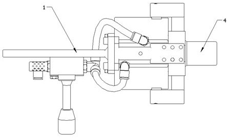
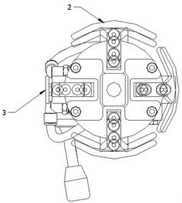

Image

  • Novel polyurethane flat steel belt winding and clamping device
  • Novel polyurethane flat steel belt winding and clamping device
  • Novel polyurethane flat steel belt winding and clamping device

Examples


Embodiment Construction

[0023] In order to make the purpose, technical solutions and advantages of the embodiments of the present invention clearer, the technical solutions in the embodiments of the present invention will be clearly and completely described below in conjunction with the accompanying drawings in the embodiments of the present invention. Obviously, the described embodiments It is some embodiments of the present invention, but not all of them. Based on the implementation manners in the present invention, all other implementation manners obtained by persons of ordinary skill in the art without creative efforts fall within the protection scope of the present invention. Accordingly, the following detailed description of the embodiments of the invention provided in the accompanying drawings is not intended to limit the scope of the claimed invention, but merely represents selected embodiments of the invention. Based on the implementation manners in the present invention, all other implement...


PUM

PropertyMeasurementUnit
The inside diameter ofaaaaaaaaaa

Abstract

The invention discloses a novel polyurethane flat steel belt winding and clamping device which comprises a four-claw air cylinder, a clamping sector piece and a clamping fixing block are installed on the outer side of the four-claw air cylinder, an air valve and an air valve installation plate are installed at one end of the four-claw air cylinder, and a clamp rotating connecting block is installed at the other end of the four-claw air cylinder. According to the novel polyurethane flat steel belt winding and clamping device, the piston area of the four-jaw air cylinder is 6.25 times that of an original finger air cylinder, the problem that a steel belt stub bar is pulled off in the winding process is solved, the clamping area of the steel belt stub bar is increased, and the risk of potential clamping marks of the steel belt stub bar is effectively avoided; after material winding is finished, a pneumatic clamping jaw retracts, the outer diameter of the clamping sector piece is reduced from 120 mm during opening to 108 mm during retracting and loosening, and the outer diameter of the clamping and winding device is completely separated from the inner diameter of a coiled material to generate a gap; and the problem that the winding and clamping device is difficult to separate from the core part of the coiled material is solved.

Description

technical field [0001] The invention relates to the technical field of polyurethane flat steel strip winding, in particular to a novel polyurethane flat steel strip winding and clamping device. Background technique [0002] The polyurethane flat steel belt for elevators is a product with multiple steel wire structures inside and polyurethane plastic wrapping on the surface. The invention is applied to the winding part of the fixed-length cutting line of the polyurethane flat steel belt. The material head cooperates with the winding table to make the steel strip that reaches the required length of the order be wound into a coil. After the coil is formed, it needs to be pulled out of the device, so that the packaging operation can be carried out from the center of the coil material in the later process. [0003] The original winding and clamping device mainly has the following two problems: the clamping force is not enough during winding, and the clamped material head of the s...

Claims


Application Information

Patent Timeline
IPC IPC(8): B65H18/02B65H18/10B65H19/30
CPCB65H18/02B65H18/10B65H19/30
Inventor 陈骏
Owner 依合斯电梯配件(上海)有限公司
Why Eureka
Try Eureka