Rapid paving method for PVC (polyvinyl chloride) plastic floor
A plastic floor, fast technology, applied in the direction of floors, buildings, building structures, etc., can solve the problems of long construction period, residual, cumbersome pavement construction, etc., and achieve the effect of high work efficiency and elimination of gaps
- Summary
- Abstract
- Description
- Claims
- Application Information
AI Technical Summary
Problems solved by technology
Method used
Image
Examples
Embodiment 1
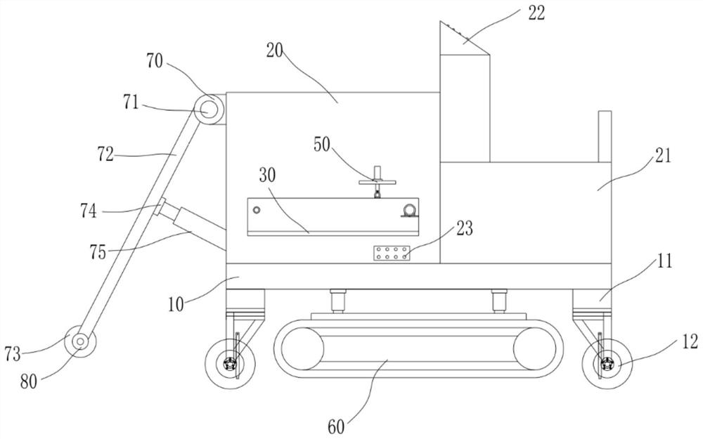
[0043] The quick paving method of PVC plastic floor includes the following steps:
[0044] S1. Clean the ground, clean up the debris on the ground, remove the dust and gravel attached to the surface of the ground, so that the ground will not be sandy;
[0045] S2, self-leveling construction, dump the self-leveling on the cleaned ground, use the paving device to scrape the self-leveling, the thickness is 3-5mm, keep ventilation, let the self-leveling dry naturally, and achieve a smooth and smooth state;
[0046] S3. Floor pre-laying, small-scale trial laying on self-leveling to ensure the color ratio of floor coverings, determine the direction of floor coverings, and mark the floor coverings;
[0047] S4. The overall paving of the floor is carried out in accordance with the order of the floor markings, and the floor is cut at the connection between the wall and the ground, so that the cut floor and the wall direction match;
[0048] S5. Floor compaction, avoid cleaning the flo...
Embodiment 2
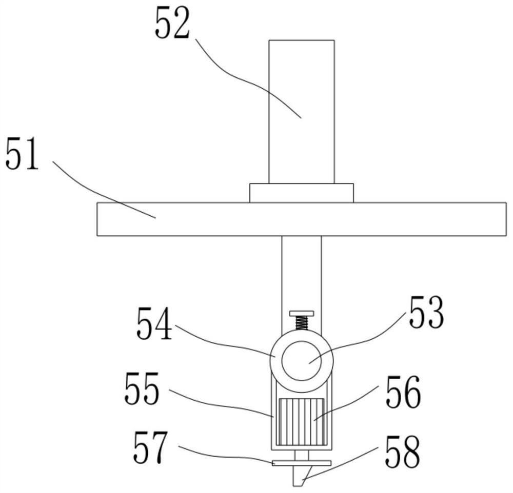
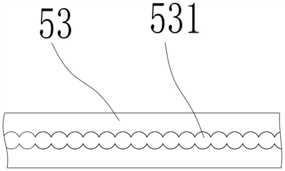
[0054] The upper side and the lower side of the guide rod 53 are respectively provided with a plurality of limit holes 531, each limit hole 531 is closely adjacent to each other on the guide rod 53, and the moving sleeve 54 is provided with a jack matching the limit holes 531. 541, a plunger 55 is movably inserted in the jack 541 and the limit hole 531, and the plunger 55 extends out of the movable sleeve 54 and is connected with a handle 551, and the plunger 55 is wound with a tension spring 56, and one end of the spring is connected to the movable sleeve 54 outer wall is connected, and the other end is connected with handle 551.
[0055] Specifically, when adjusting the position of the moving sleeve 54 on the guide rod 53, pull the insertion rod 55 through the handle 551, so that the insertion rod 55 is disengaged from the side limit hole 531, and the moving sleeve 54 is moved on the guide rod 53, and then Loosen the plunger 55, and the plunger 55 is plugged in other limit h...
Embodiment 3
[0057] The feeding mechanism includes a first shelf 32, a second shelf 31, a driving roller 41, a driven roller 42, a conveyor belt 43 and a drive motor 40, the first shelf 32 is fixed on the inside of the horizontal plate 30, and the second shelf The plate 31 is fixed on the outside of the horizontal plate 30, the driving roller 41 is arranged above one end of the horizontal plate 30 and is connected to the first frame plate 32 and the second frame plate 31 in rotation, and the driven roller 42 is arranged above the other end of the horizontal plate 30 and connected to the first frame plate 30. The frame plate 32 and the second frame plate 31 are rotationally connected, the drive motor 40 is fixed on the outer wall of the second frame plate 31, the drive motor 40 is driven and connected with the driving roller 41, and the conveyor belt 43 is sleeved on the driving roller 41 and the driven roller 42 On the upper surface of the conveyor belt 43, several groups of anti-slip conve...
PUM
 Abstract
Description
Claims
Application Information
 - R&D
- Intellectual Property
- Life Sciences
- Materials
- Tech Scout
- Unparalleled Data Quality
- Higher Quality Content
- 60% Fewer Hallucinations
Browse by: Latest US Patents, China's latest patents, Technical Efficacy Thesaurus, Application Domain, Technology Topic, Popular Technical Reports.
© 2025 PatSnap. All rights reserved.Legal|Privacy policy|Modern Slavery Act Transparency Statement|Sitemap|About US| Contact US: help@patsnap.com


