Medium-high pressure natural gas flow path switching device and using method

A switching device, natural gas technology, applied in the valve device for absorbing fluid energy, valve device, valve operation/release device, etc. The effect of prolonging the service life

Inactive Publication Date: 2021-04-06
PETROCHINA CO LTD
View PDF6 Cites 0 Cited by
  • Summary
  • Abstract
  • Description
  • Claims
  • Application Information

AI Technical Summary

Problems solved by technology

[0003] According to the number of metering separators in the gas gathering station, it is necessary to switch the process of 2 to 3 groups of gas wells every day. According to the operation sequence of "open first and then close", a total of 8 to 12 hand valves in 4 to 6 wells need to be switched on and off. , more than two people are required to operate, the degree of valve rust is different, the operation volume is large, and there is a risk of the valve stem popping out and hurting people

Method used


Image

  • Medium-high pressure natural gas flow path switching device and using method

Examples


Embodiment 1

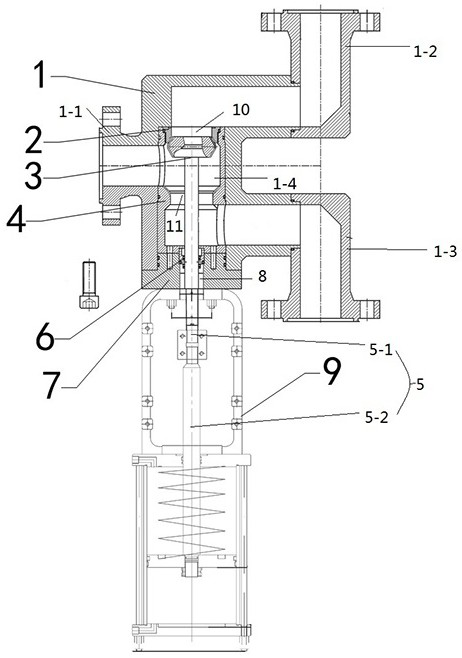
[0020] Such as figure 1 As shown, a medium-high pressure natural gas process switching device includes a valve body 1 and a pneumatic device connected to the valve body 1, and the valve body 1 includes an inlet 1-1, a first outlet 1-2, and a second outlet 1-3 And the separation chamber 1-4, the inlet 1-1, the first outlet 1-2 and the second outlet 1-3 all communicate with the separation chamber 1-4 through passages, the first outlet 1-2 and the second outlet 1 -3 Connected with the separation chamber 1-4 are the first interface 10 and the second interface 11 respectively, the pneumatic device includes a pneumatic driver 9 and a valve stem 5 connected to the pneumatic driver 9, the pneumatic driver 9 is connected to the valve body 1, the valve The stem extends into the separation chamber 1-4 through the second interface 11, and the top end of the valve stem 5 is connected with a valve stem disc 3, which matches the first outlet 1-2 and the second outlet 1-3.

[0021] The valve...

Embodiment 2

[0025] Such as figure 1 As shown, on the basis of Embodiment 1, flanges are provided at the inlet 1-1, the first outlet 1-2 and the second outlet 1-3. The inlet 1-1, the first outlet 1-2 and the second outlet 1-3 are all arranged in a flange shape, and are connected with upstream and downstream pipelines through flanges and screws.

[0026] The valve seat 2 is connected to the first interface 10 .

[0027] The valve stem sleeve 4 is connected to the second interface 11 .

[0028] A valve seat 2 is connected to the inner wall of the channel at the first interface 10 , so that the valve seat 2 is in contact with the valve stem disc 3 to form a seal. The valve stem sleeve 4 is also connected to the second interface 11 , so that the valve stem sleeve 4 forms a seal with the valve stem disc 3 .

[0029] The valve body 1 is connected with an end cover 7, and the other side of the end cover 7 is connected with a pneumatic driver 9, and the valve stem 5 passes through the end cover...

Embodiment 3

[0042] Such as figure 1As shown, on the basis of Example 2, a method of using a medium-high pressure natural gas process switching device, when in the metering process, the pneumatic driver 9 is activated to push the valve stem 5 upward until the valve stem disc 3 contacts the valve seat 2 And seal, block the first interface 10, the gas entering from the inlet 1-1 passes through the separation chamber 1-4, the second interface 11, and finally discharges from the second outlet 1-3; when in the production process, the pneumatic drive 9 Close, the valve stem 5 goes down until the lower end of the valve stem disc 3 contacts with the valve stem sleeve 4 and forms a seal, forming a seal for the second interface 11, and the gas entering from the inlet 1-1 is discharged from the first outlet 1-2.

[0043] There are two types of processes, metering process and production process. During the metering process, there is little gas from the inlet 1-1, and generally only one upstream pipel...


PUM


Abstract

The invention discloses a middle-high pressure natural gas flow path switching device and a using method. The middle-high pressure natural gas flow path switching device comprises a valve body and a pneumatic device connected with the valve body, the valve body comprises an inlet, a first outlet, a second outlet and a separation cavity, the inlet, the first outlet and the second outlet communicate with the separation cavity through channels, a first connector and a second connector are arranged at the joint of the first outlet and the separation cavity and the joint of the second outlet and the separation cavity separately, the pneumatic device comprises a pneumatic driver and a valve rod connected with the pneumatic driver, the pneumatic driver is connected to the valve body, the valve rod penetrates through the second connector to extend into the separation cavity, the top end of the valve rod is connected with a valve rod valve clack, and the valve rod valve clack is matched with the first outlet and the second outlet. The valve rod and the valve rod valve clack are controlled to move through the pneumatic driver, so that the first connector or the second connector is blocked, process switching is achieved, and remote process switching can be achieved by remotely controlling the pneumatic driver.

Description

technical field [0001] The invention belongs to the technical field of valves, and in particular relates to a medium-high pressure natural gas process switching device and a use method. Background technique [0002] The natural gas enters the gas gathering station, is heated by the heating furnace, and then reaches the throttling area. After the needle valve in the throttling area regulates the natural gas flow, the pipeline is divided into two, and enters the production or metering separator through the hand valve. Inverting order quantity is an important task of process switching in gas gathering stations. Through process switching, the production of gas wells can be measured and the production dynamics of gas wells can be understood. [0003] According to the number of metering separators in the gas gathering station, it is necessary to switch the process of 2 to 3 groups of gas wells every day. According to the operation sequence of "open first and then close", a total o...

Claims


Application Information

Patent Timeline
Patent Type & Authority Applications(China)
IPC IPC(8): F16K11/044F16K31/122F16K47/02
CPCF16K11/044F16K31/1221F16K47/023
Inventor 张昀张向京左一楠苗成苟景卫王良李娟娟
Owner PETROCHINA CO LTD
Why Eureka
Try Eureka