
Resistance rudder low-speed flutter wind tunnel model with flutter suppression device

A technology for suppressing device and resistance, applied in the field of low-speed flutter wind tunnel model of resistance rudder, can solve the problems of long reaction time, large deflection angle, and poor effect of suppressing sudden flutter, so as to achieve accurate simulation and suppress rudder surface. Vibration, weight reduction effect

Active Publication Date: 2021-04-06
SHENYANG AIRCRAFT DESIGN INST AVIATION IND CORP OF CHINA
View PDF6 Cites 2 Cited by
  • Summary
  • Abstract
  • Description
  • Claims
  • Application Information

AI Technical Summary

Problems solved by technology

[0003] Unlike conventional wings, the premise of small attack angle, small deflection angle and small amplitude vibration of the aileron structure, the drag rudder usually has a large deflection angle because it needs to participate in yaw control, which gives the flutter of the drag rudder structure Difficulty with model design
At the same time, in the wind tunnel test, the flutter model with a resistance rudder structure generally adopts the method of reducing the wind speed of the wind tunnel to suppress the flutter phenomenon, and the reaction time is relatively long, which is not effective in suppressing sudden flutter.

Method used


Image

  • Resistance rudder low-speed flutter wind tunnel model with flutter suppression device
  • Resistance rudder low-speed flutter wind tunnel model with flutter suppression device
  • Resistance rudder low-speed flutter wind tunnel model with flutter suppression device

Examples


Embodiment Construction

[0035] In order to make the purpose, technical solution and advantages of the application more clear, the technical solution in the embodiment of the application will be described in more detail below in conjunction with the drawings in the embodiment of the application. In the drawings, the same or similar reference numerals denote the same or similar elements or elements having the same or similar functions throughout. The described embodiments are some, but not all, embodiments of the application. The embodiments described below by referring to the figures are exemplary, and are intended to explain the present application, and should not be construed as limiting the present application. Based on the embodiments in this application, all other embodiments obtained by persons of ordinary skill in the art without creative efforts fall within the protection scope of this application. Embodiments of the present application will be described in detail below in conjunction with th...


PUM


Abstract

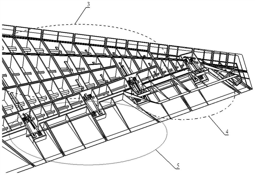
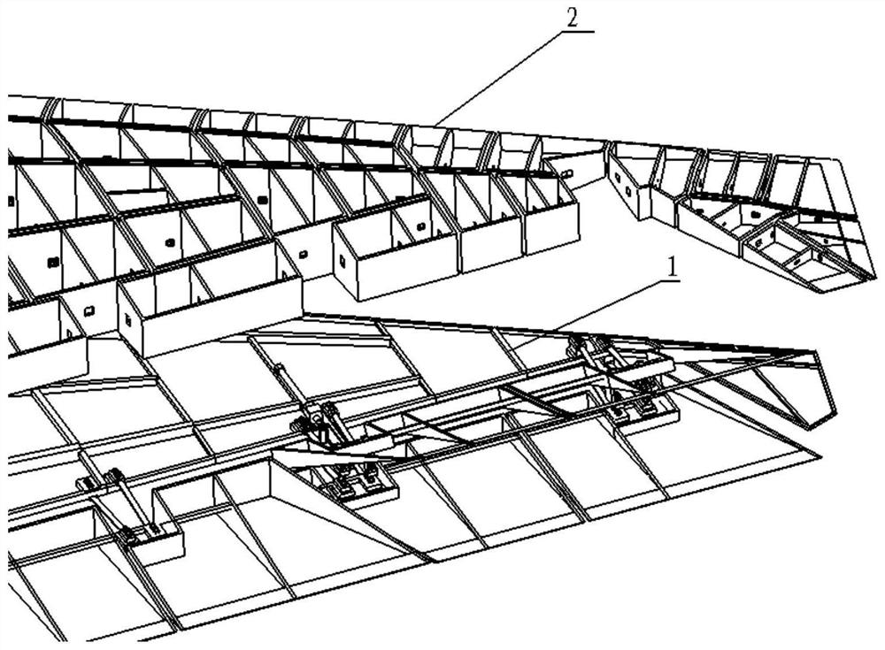
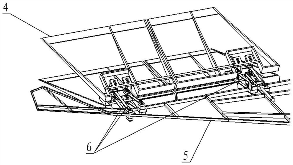
The invention belongs to the technical field of flutter wind tunnel tests, and particularly relates to a resistance rudder low-speed flutter wind tunnel model with a flutter suppression device. The model comprises a main wing surface and a resistance rudder, the resistance rudder is installed on the rear edge of the main wing surface through an installation assembly, and the installation assembly comprises a spring piece, a control surface deflection piece, a pneumatic element, a brake pin and a guide rail. The resistance rudder low-speed flutter wind tunnel model with the flutter suppression device has suppression capability when a flutter phenomenon occurs in the model resistance rudder in a wind tunnel test, the weight of related mechanisms is greatly reduced, and the simulation of the model is more accurate. The model has the function of selecting the upper control surface and the lower control surface to simultaneously suppress or only suppress the vibration of the upper control surface or the lower control surface by replacing brake pins in different forms, is suitable for flutter model design with a resistance rudder structure, and verifies flutter characteristics and flutter speed allowance related to a certain type of aircraft resistance rudder in a test.

Description

technical field [0001] The application belongs to the field of flutter wind tunnel test technology, in particular to a low-speed flutter wind tunnel model of a drag rudder with a flutter suppression device. Background technique [0002] Drag rudder is one of the most effective directional control measures for aircraft with tailless flying wing layout. Generally, the split trailing edge drag rudder is the most common, and drag rudder is usually installed near the wingtip. The analysis of flutter characteristics related to drag rudder needs to be verified by wind tunnel test. [0003] Unlike conventional wings, the premise of small attack angle, small deflection angle and small amplitude vibration of the aileron structure, the drag rudder usually has a large deflection angle because it needs to participate in yaw control, which gives the flutter of the drag rudder structure Model design poses difficulties. At the same time, in the wind tunnel test, the flutter model with a d...

Claims


Application Information

Patent Timeline
IPC IPC(8): G01M9/08B64F5/60F16F15/073
CPCG01M9/08B64F5/60F16F15/073
Inventor 胡鑫于佳鑫赵飞宇脱朝智王赫喆
Owner SHENYANG AIRCRAFT DESIGN INST AVIATION IND CORP OF CHINA
Learn More