Electric welding structure of cable joint

A cable joint and welding structure technology, applied in the direction of cable joints, cable terminals, etc., can solve the problems of excessive material usage, material leakage, stacking collapse, etc., and achieve the effect of shortened construction operation time, accurate standard positioning, and simple and fast operation.

Pending Publication Date: 2021-04-06
珠海海德有色金属新材科技有限公司
View PDF0 Cites 0 Cited by
  • Summary
  • Abstract
  • Description
  • Claims
  • Application Information

AI Technical Summary

Problems solved by technology

[0003] Its biggest disadvantage and potential safety hazard is that the liquefied gas tank is heated by a torch spray gun at close range, and the simple protective equipment and temperature-resistant cloth are used to smear, stack, and wrap with the palm of one hand, resulting in explosions and high-temperature burns. It is extremely dangerous, because the construction process is done by bare hands, and the amount and temperature of stacking required each time are estimated based on experience, and it is stacked with one hand and bare hands, which causes deviations in the amount and temperature, and the amount is too much Overflowing and wasting from the palm of the hand. If the temperature is high, the palm of the hand can’t bear the high temperature through the cloth for a long time. , you need to heat it with an open flame, then apply it with bare hands again, shape it, and repeat it many times until it is completely covered
Moreover, the disadvantage of this technology is that the waste of lead-tin alloy strips is serious during the operation process, because the above-mentioned whole process is all manual operation, experience judgment, no quantification, measurement, detection tools and means, it is bound to Cause defects such as heap collapse, lead flow, material leakage and excessive use of materials; and this technical operation is dangerous and depends on human factors, environment, weather, time, construction site and other factors. The construction time is 2- 3 hours

Method used


Image

  • Electric welding structure of cable joint
  • Electric welding structure of cable joint
  • Electric welding structure of cable joint

Examples


Embodiment Construction

[0024] The embodiments of the present invention will be described in detail below in conjunction with the accompanying drawings. Apparently, the described embodiments are only some of the embodiments of the present invention, not all of them.

[0025] In describing the present invention, it should be understood that the terms "upper", "lower", "front", "rear", "left", "right", "top", "bottom", "inner", " The orientation or positional relationship indicated by "outside", etc. is based on the orientation or positional relationship shown in the drawings, and is only for the convenience of describing the present invention and simplifying the description, rather than indicating or implying that the referred device or element must have a specific orientation, so as to Specific orientation configurations and operations, therefore, are not to be construed as limitations on the invention.

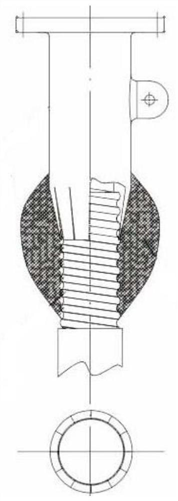
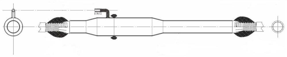
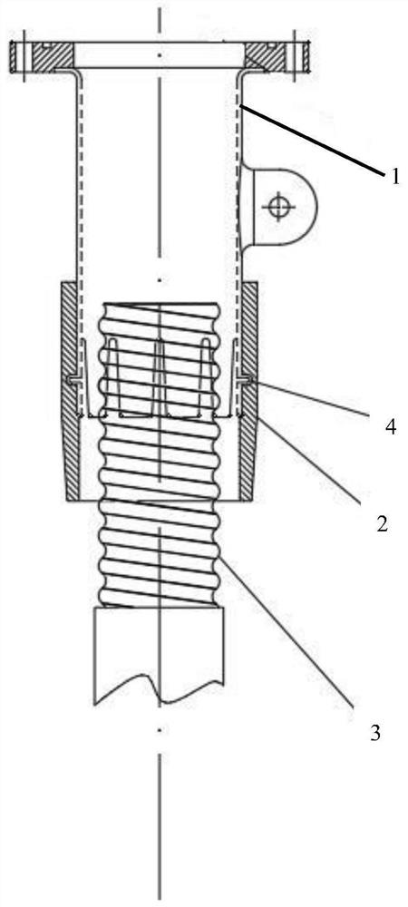
[0026] An electrical welding structure for a cable joint, comprising a cable joint copper shell ...


PUM


Abstract

The invention discloses an electric welding structure of a cable joint. The electric welding structure comprises a cable joint copper shell, a welding sleeve and a cable, the cable joint copper shell is provided with a tail end part connected with a cable, and the tail end part is provided with a plurality of furling sheets to form a furling opening; the cable comprises an aluminum sheath, and the aluminum sheath at the connecting end of the copper shell of the cable joint is inserted into the closing opening to be crossed and overlapped with the tail end part; and the welding sleeve is sleeved outside the crossed and overlapped part of the cable and the tail end part, and the cable joint copper shell and the cable are welded together through the welding sleeve. The structure has the advantages of modularization, standardization, no waste, low energy consumption, electrification safety construction, simplicity, convenience and quickness in operation and the like; more scientific, more reliable and safer connection between the copper shell of the power cable intermediate joint and the cable aluminum sheath pipe is ensured; and the structure is not influenced by various human factors, environments, weather, time, construction sites and other factors, and the construction time is shortened to 10-20 minutes.

Description

technical field [0001] The invention relates to the field of connection technology and product technology between a copper shell of a power cable joint of a high-voltage transmission and transformation line and an aluminum sheath tube of a cable, and in particular relates to an electric welding structure of a cable joint. Background technique [0002] The connection between the cable and the copper shell of the cable joint is a common connection method for cables. At present, manual welding is generally used. First, the cable is stripped out of the exposed aluminum sheath of the cable according to the installation process of the cable intermediate joint, and the cable is sprayed with a liquefied gas torch. Heat and plate a layer of metal tin as the base at the same time as the end of the copper shell, then heat the lead-aluminum-tin alloy strip to a semi-molten (about 150-200°C) state in a heat-resistant cloth, smear and stack it on the copper and aluminum At the joint, repe...

Claims


Application Information

Patent Timeline
IPC IPC(8): H02G15/08H02G15/06
CPCH02G15/06H02G15/08
Inventor 陈德清孟平邹嘉运
Owner 珠海海德有色金属新材科技有限公司
Why Eureka
Try Eureka