Self-expanding locking interface implant package

An implant and self-expanding technology, applied in the fields of implantology, medical science, dentistry, etc., can solve the problems of excessive occlusal pressure around the artificial teeth, shaking of the abutment (artificial teeth), long time-consuming and low efficiency, etc., to improve the implantation efficiency. The effect of success rate, increased risk of fracture resistance, and convenient processing

Pending Publication Date: 2021-04-09
JIANGYIN JINTAIKE BIOTECH
View PDF0 Cites 0 Cited by
  • Summary
  • Abstract
  • Description
  • Claims
  • Application Information

AI Technical Summary

Problems solved by technology

In the prior art, as far as the conventional implant structure is concerned, the fixed body and the abutment have a threaded connection structure. During the process of chewing food, due to the repeated application of continuous load in the oral cavity, the screw vibrates slightly, and the amplitude gradually increases. , it is easy to cause rotation, leading to loose threads, resulting in a gap between the implant and the abutment, causing the abutment, that is, the artificial tooth to shake, and causing excessive occlusal pressure around the artificial tooth, etc.
[0003] In addition, the above-mentioned traditional implant connection structure needs to drill the inside of the implant and then process the screw. Because the screw hole is small and deep, the processing is difficult, time-consuming, long-term and inefficient.

Method used


Image

  • Self-expanding locking interface implant package
  • Self-expanding locking interface implant package
  • Self-expanding locking interface implant package

Examples


Embodiment Construction

[0031] The specific embodiments of the present invention will be described below in conjunction with the accompanying drawings.

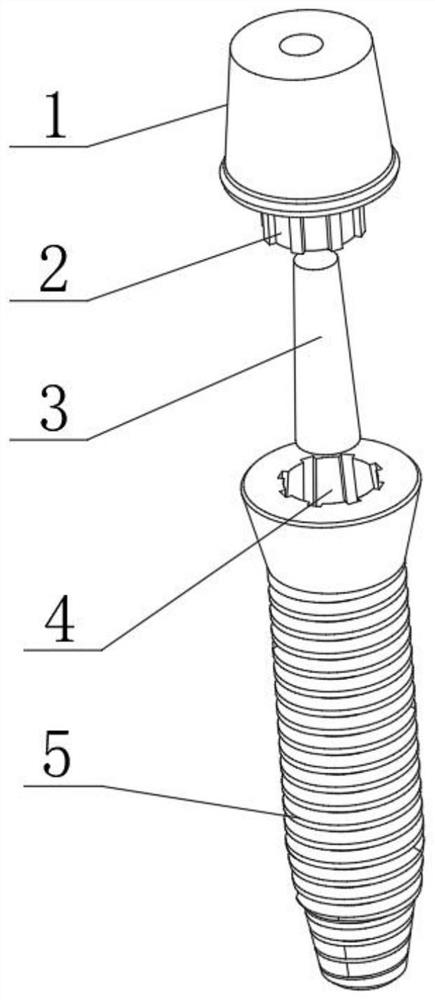
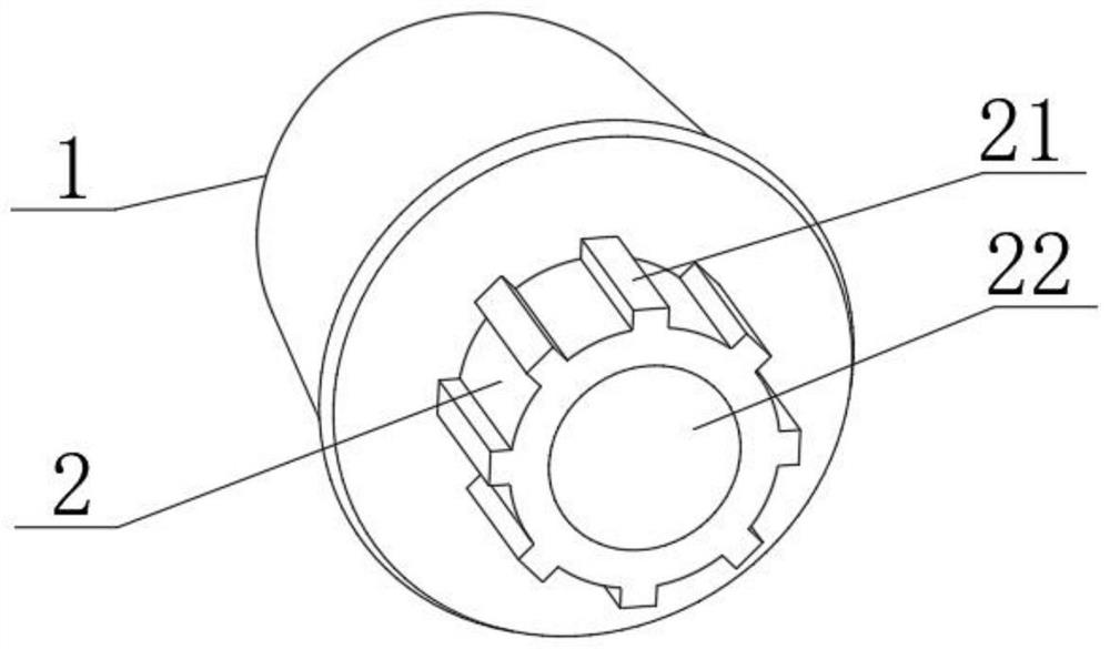
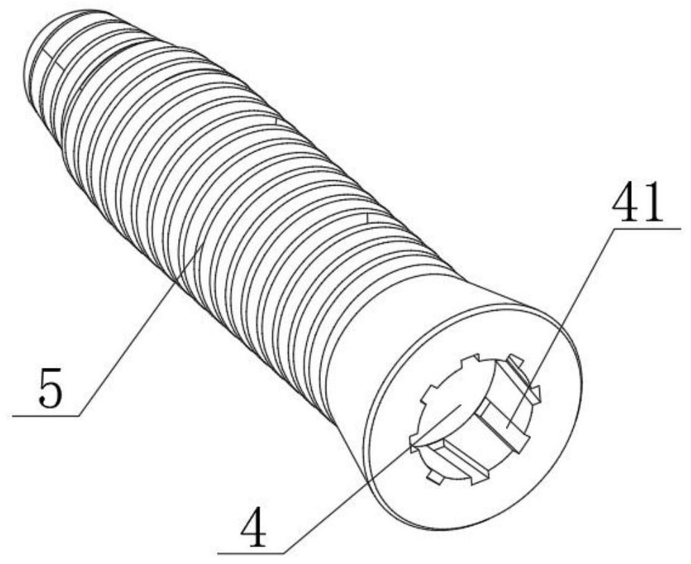
[0032] Such as Figure 1-Figure 4 As shown, the self-expanding locking interface implant set of this embodiment includes an implant 5 and an abutment 1, an inner groove body 4 is provided at one end of the implant 5, and an outer convex tube body 2 is formed at one end of the abutment 1, The protruding tube body 2 is an elastic part, and a hole 22 is formed in it; it also includes an inlay 3, which is used for nested fitting with the hole body 22, and the protruding tube body 2 is elastically deformed during the fitting process. , so that the outer convex pipe body 2 and the inner groove body 4 are fitted in a nested manner to form an elastic connection structure.

[0033] Such as Figure 4 and Figure 5 As shown, an outer conical surface 31 is formed on the outside of the inlay 3, and a corresponding inner conical surface 23 is formed on the inn...


PUM


Abstract

The invention provides a self-expanding locking interface implant package. The self-expanding locking interface implant package comprises an implant and an abutment, one end of the implant is provided with an inner concave groove body, an outer convex pipe body is formed at one end of the abutment, an elastic piece, and internally provided with a hole body; the self-expanding locking interface implant package also comprises an embedded body, the embedded body is used for being matched with the hole body in a nested mode, after the outer convex pipe body is elastically deformed in a matching process, and the outer convex pipe body and the inner concave groove body are matched in a nested mode to form an elastic connecting structure; an outer conical surface is formed on an outer side of the embedded body and a corresponding inner conical surface is formed on an inner side of the hole body; and when the inner conical surface is sleeved from a large-diameter end of the inner conical surface to a small-diameter end of the outer conical surface in an axial direction, a size of the outer convex pipe body is gradually expanded in a radial direction, and after the sleeving is completed, the outer convex pipe body and the inner concave groove body are connected in a complementary mode. By means of an elastic nesting fit of the embedded body and the outer convex pipe body, the outer convex pipe body and the inner concave groove body form the complementary concave-convex combined type elastic connecting structure, the abutment can be effectively prevented from disengaging, structural reliability is high, and stability is good.

Description

technical field [0001] The invention relates to the technical field of dental implants, in particular to a self-expanding locking interface implant kit. Background technique [0002] The method of implanting teeth in dental surgery is to implant a fixed body (implant) into the jawbone, and then add prosthetics such as artificial teeth through a fixed abutment to restore the normal function of the teeth. In the prior art, as far as the conventional implant structure is concerned, the fixed body and the abutment have a threaded connection structure. During the process of chewing food, due to the repeated application of continuous load in the oral cavity, the screw vibrates slightly, and the amplitude gradually increases. , It is easy to cause rotation, resulting in loose threads, resulting in a gap between the implant and the abutment, causing the abutment, that is, the artificial tooth to shake, and causing problems such as excessive occlusal pressure around the artificial to...

Claims


Application Information

Patent Timeline
Patent Type & Authority Applications(China)
IPC IPC(8): A61C8/00
CPCA61C8/0012A61C8/0037A61C8/005A61C8/0071A61C8/0074
Inventor 张杰许钦徐涛
Owner JIANGYIN JINTAIKE BIOTECH
Why Eureka
Try Eureka