
Method for detecting parallelism of movement of heavy vertical lathe vertical tool rest to working table

A technology of vertical tool post and vertical lathe, applied in the direction of manufacturing tools, metal processing equipment, measuring/indicating equipment, etc., it can solve problems such as difficult operation, error, deflection and deformation, and achieve high efficiency, high precision and simple operation convenient effect

Inactive Publication Date: 2021-04-09
齐重数控装备股份有限公司
View PDF11 Cites 0 Cited by
  • Summary
  • Abstract
  • Description
  • Claims
  • Application Information

AI Technical Summary

Problems solved by technology

[0003] However, when inspecting heavy vertical lathes, as the machine tool specifications increase, the size of the span and level gauges also gradually increases.
It is difficult to meet the precision requirements when processing the long-distance flat gauge. The flat gauge is affected by the gravity field during the inspection, resulting in deflection and deformation. There is a certain error between the measurement result and the real value.
It is also necessary to adjust the parallelism between the level gauge and the worktable during inspection, and this method is relatively difficult to operate

Method used


Image

  • Method for detecting parallelism of movement of heavy vertical lathe vertical tool rest to working table
  • Method for detecting parallelism of movement of heavy vertical lathe vertical tool rest to working table
  • Method for detecting parallelism of movement of heavy vertical lathe vertical tool rest to working table

Examples


Embodiment Construction

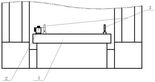
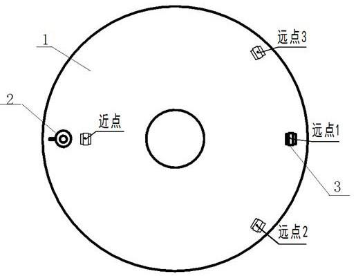
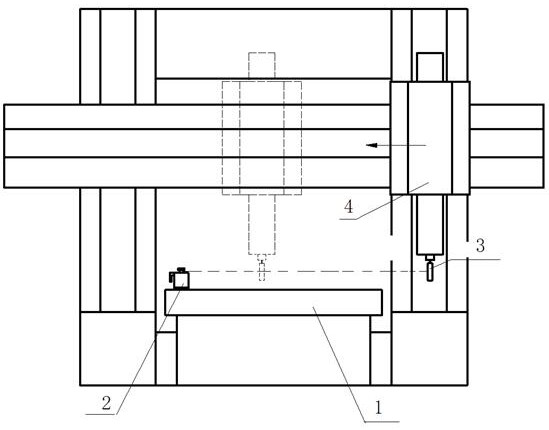
[0014] Such as Figure 1-3 As shown, a method for detecting the parallelism of the vertical tool rest movement of a heavy-duty vertical lathe to the worktable surface is to place the laser transmitter 2 of the laser geometry measuring instrument at a position on the workbench 1 that can scan the area of ​​the vertical tool rest 4, and use The laser receiver 3 of the laser geometry measuring instrument is set to zero at the near point and zero at the far point. Adjust the rotating laser surface of the laser transmitter 2 to be parallel to the surface of the workbench 1 to establish a reference plane. In order to establish a reference plane The accuracy is adjusted by the laser receiver 3 again at the three far points, the laser receiver 3 is placed on the vertical knife holder 4, and the receiver 3 is adjusted to receive the range of the rotating laser plane, and the vertical knife is started. Frame 4 is used for detection, and the laser geometry measuring instrument is used to...


PUM


Abstract

The invention discloses a method for detecting the parallelism of movement of a heavy vertical lathe vertical tool rest to a working table, and belongs to the technical field of machine tool precision detection. A laser emitter of a laser geometry measuring instrument is placed at the position, capable of scanning the area of a vertical tool rest, of a workbench, the rotating laser face of the laser emitter is adjusted to be parallel to the surface of the workbench through the method of near-point zero setting and far-point zero setting of laser receivers of the laser geometry measuring instrument, and a reference plane is established. In order to establish the accuracy of the reference plane, the laser receivers are aligned again at three positions of a far point, the laser receivers are placed on the vertical knife rest, the vertical knife rest is started for detection when the receivers are adjusted to receive the range of the rotating laser plane, numerical values of all the positions on a stroke are read through the laser geometric measuring instrument, data processing is carried out, and the parallelism errors of the movement of the vertical tool rest and the surface of the workbench are calculated.

Description

technical field [0001] The invention relates to a method for detecting the parallelism of the movement of the vertical tool rest of a heavy-duty vertical lathe to the working surface, and belongs to the technical field of machine tool precision detection. Background technique [0002] At present, in the machine tool manufacturing industry, the G5 accuracy of the vertical lathe, that is, the detection of the parallelism of the worktable surface by the movement of the vertical tool holder, is usually detected with the aid of a flat ruler. The method is to place a square ruler on the workbench parallel to the front guide rail surface of the crossbeam, and turn the workbench to adjust the two ends of the ruler to "zero" on the side of the tool holder, so that the ruler is parallel to the workbench and the indicator is fixed. On the vertical turret, make the probe touch the inspection surface of the ruler, and move the vertical turret for inspection. [0003] However, when inspe...

Claims


Application Information

Patent Timeline
Patent Type & Authority Applications(China)
IPC IPC(8): B23Q17/24B23Q17/22
CPCB23Q17/24B23Q17/22
Inventor 陈光远徐忠和刘双江夏丽娟张庆邢春艳曹雨赵朋飞杨嘉武林孙长龙刘旭通宋广文刘文凡
Owner 齐重数控装备股份有限公司
Learn More