

Lifting type manipulator feeding and discharging structure
A manipulator, pull-type technology, applied in the field of bearing grinding, can solve the problems of many types of manipulator parts, long automatic loading and unloading time, easy damage to the outer circle precision of bearing rings, etc.
- Summary
- Abstract
- Description
- Claims
- Application Information
AI Technical Summary
Problems solved by technology
Method used
Image

Examples
Embodiment Construction
[0024] The present invention will be described in detail below in conjunction with the accompanying drawings. Embodiments of the present invention are described in detail below, examples of which are shown in the drawings, wherein the same or similar reference numerals designate the same or similar elements or elements having the same or similar functions throughout. The embodiments described below by referring to the figures are exemplary only for explaining the present invention and should not be construed as limiting the present invention. The orientation terms such as left, center, right, up, and down in the examples of the present invention are only relative concepts or refer to the normal use state of the product, and should not be considered as limiting.
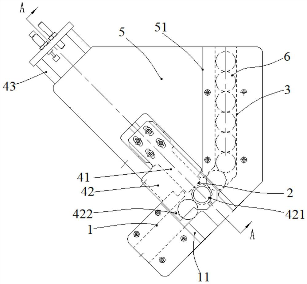
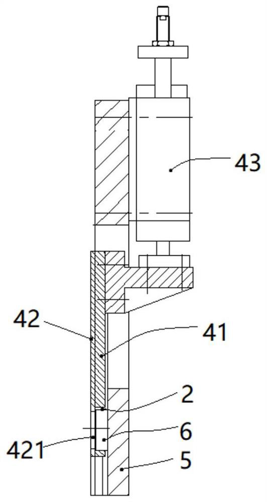
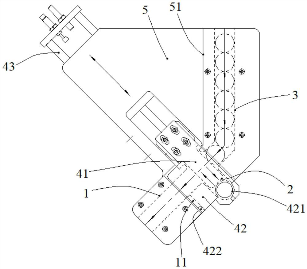
[0025] A lifting type manipulator loading and unloading structure, such as figure 1 with image 3 As shown, it includes a manipulator and a first feeding channel 1 arranged obliquely, the manipulator is arranged th...
PUM
 Abstract
Description
Claims
Application Information