
Grinding machine capable of fixing drum brake pads of different models and for drum brake machining

A brake pad and drum type technology, which is applied in the field of drum brake pad grinding machines with different types of fixed drum brake pads, can solve the problems of increasing processing costs, cumbersome process, and reducing work efficiency.

Inactive Publication Date: 2021-04-09
高邮市精正机械制造有限公司
View PDF0 Cites 0 Cited by
  • Summary
  • Abstract
  • Description
  • Claims
  • Application Information

AI Technical Summary

Problems solved by technology

[0002] Drum brake processing During processing, drum brake pads are one of the components used for installation. In the production of brake pads, the inner and outer arc surfaces of the brake pads must be ground. The traditional method is to fix the brake pads and then The grinding device processes the brake pads. During the processing, the brake pads need to be firmly fixed at the designated position. Due to the different models of the car, the size of the brake pads required is also different. The traditional processing grinder processes different brake pads. When it is necessary to replace the fixed mold of the same size, the process is cumbersome and increases the processing cost. At the same time, after the inner arc surface is polished, the brake pad needs to be reassembled for outer arc surface grinding, which reduces work efficiency. Therefore, we propose a Different types of drum brake pad grinding machines can be fixed for drum brake processing

Method used

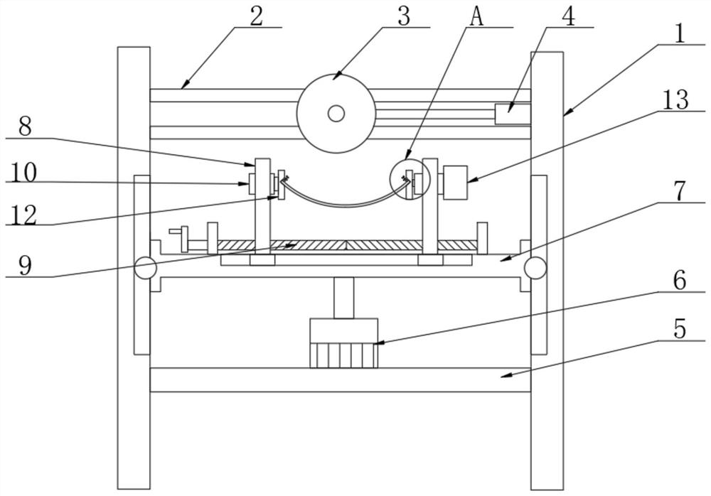
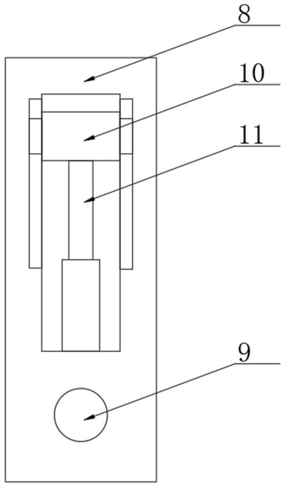
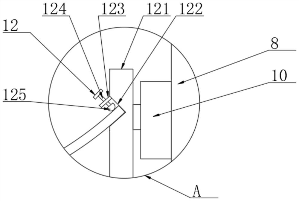

Image

  • Grinding machine capable of fixing drum brake pads of different models and for drum brake machining
  • Grinding machine capable of fixing drum brake pads of different models and for drum brake machining
  • Grinding machine capable of fixing drum brake pads of different models and for drum brake machining

Examples


Embodiment Construction

[0015] The following will clearly and completely describe the technical solutions in the embodiments of the present invention with reference to the accompanying drawings in the embodiments of the present invention. Obviously, the described embodiments are only some, not all, embodiments of the present invention. Based on the embodiments of the present invention, all other embodiments obtained by persons of ordinary skill in the art without making creative efforts belong to the protection scope of the present invention.

[0016] see Figure 1-3 , the present invention provides a technical solution: a drum brake grinding machine that can fix different types of drum brake pads for processing, please refer to figure 1 , it should be noted that the electrical components in the present invention are all connected to the external power supply through wires, including two sets of mounting frames 1, and two sets of slide rails 2 are symmetrically fixed on the upper positions between th...


PUM


Abstract

The invention discloses a grinding machine capable of fixing drum brake pads of different models and for drum brake machining in the technical field of drum brake machining. The grinding machine comprises two sets of mounting racks, a first cylinder is fixedly arranged at the top of the left outer wall of the mounting rack on the right side, the output end of a second cylinder is fixedly connected with the center of the bottom of a movable seat through a piston rod, two sets of supporting seats are arranged at the top of the movable seat in a sliding manner, through openings are vertically formed in the two sets of supporting seats, clamping pieces of the same structure are arranged on the inner sides of two sets of movable blocks, and rotating rods are fixedly arranged on the sides, opposite to each other, of the two sets of clamping pieces. According to the grinding machine, a bidirectional lead screw and the two sets of supporting seats are arranged, during use, the distance between the two sets of supporting seats can be adjusted according to the length of a brake pad, the brake pad can be stably fixed through the arranged clamping pieces and can be adjusted and fixed according to the thickness of the brake pad, operation stability is guaranteed, use is convenient, and work efficiency is greatly improved.

Description

technical field [0001] The invention relates to the technical field of drum brake processing, in particular to a drum brake pad grinder which can fix different types of drum brake pads for processing drum brakes. Background technique [0002] Drum brake processing During processing, drum brake pads are one of the components used for installation. In the production of brake pads, the inner and outer arc surfaces of the brake pads must be ground. The traditional method is to fix the brake pads and then The grinding device processes the brake pads. During the processing, the brake pads need to be firmly fixed at the designated position. Due to the different models of the car, the size of the brake pads required is also different. The traditional processing grinder processes different brake pads. When it is necessary to replace the fixed mold of the same size, the process is cumbersome and increases the processing cost. At the same time, after the inner arc surface is polished, ...

Claims


Application Information

Patent Timeline
IPC IPC(8): B24B19/28B24B41/06B24B41/02B24B47/12B24B47/04
CPCB24B19/28B24B41/02B24B41/067B24B47/04B24B47/12
Inventor 乔爱民
Owner 高邮市精正机械制造有限公司
Learn More