
High-precision adjustable positioning device and method for processing and testing shaft parts

A technology of shaft parts and positioning devices, which is applied in the direction of measuring devices, optical devices, workpiece clamping devices, etc., can solve the problems of adjustment and precise positioning without high precision, and achieve low cost, convenient adjustment, and easy operation Effect

Active Publication Date: 2021-09-24
DALIAN UNIV OF TECH
View PDF10 Cites 0 Cited by
  • Summary
  • Abstract
  • Description
  • Claims
  • Application Information

AI Technical Summary

Problems solved by technology

Because the device is driven by bolts, it does not have the ability of high-precision adjustment and precise positioning

Method used


Image

  • High-precision adjustable positioning device and method for processing and testing shaft parts
  • High-precision adjustable positioning device and method for processing and testing shaft parts
  • High-precision adjustable positioning device and method for processing and testing shaft parts

Examples


Embodiment Construction

[0023] The method for assembling and using a high-precision adjustable positioning device for processing and testing shaft parts includes the following steps:

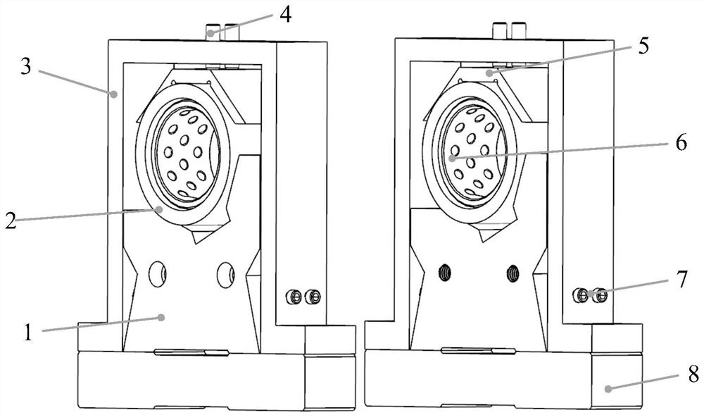
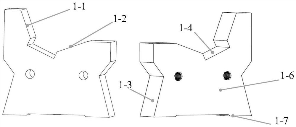
[0024] 1) Before assembly, use the high-precision grinding plate that has been ground to refine the knife-edge ruler, which will more than double the accuracy of the knife-edge ruler; use the above-mentioned high-precision grinding plate to fine-tune the connecting surfaces 1-6 of the asymmetric V-shaped block 1 , the positioning surface 1-7, the upper and lower sides of the cushion block 8 and the bottom surface of the fixed frame 3 are refined;

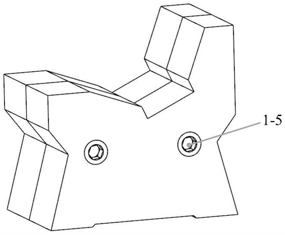
[0025] 2) The two asymmetric V-shaped blocks 1 are processed synchronously with GCr15 material. The two working surfaces are perpendicular to each other, and the angles with the horizontal plane are respectively 70° and 20°, and the adjustment surfaces 1-3 are at 75° with the horizontal plane. In order to ensure its dimensional consistency, the two asymmetric V-shaped blocks...


PUM


Abstract

The invention belongs to the field of precision machining technology and measurement technology, and relates to a high-precision adjustable positioning device and method for machining and testing shaft parts. The device includes: two asymmetrical V-shaped blocks, two pads, two fixed frames, two copper pressure blocks, two bearing outer rings, and two dense bead shaft sleeves. Through the combined use of three methods acting on the working surface, adjustment surface, and positioning surface of the asymmetric block V-shaped block, the multi-degree-of-freedom adjustment of the horizontal translation, rotation, and vertical translation of the shaft parts is realized. The device can judge the installation accuracy of the bus bar of shaft parts by the light gap method. The utility model has the advantages of simple operation, convenient adjustment, low cost, etc., and has important popularization and application value.

Description

technical field [0001] The invention belongs to the technical field of precision machining and measurement, and relates to a high-precision adjustable positioning device and an adjustment method for the machining and detection of shaft parts. Background technique [0002] The shaft is a typical part of the machine, it supports the rotation of other rotating parts and transmits torque, and is connected with the frame of the machine through bearings at the same time. Shaft parts are used as the measurement reference when measuring workpieces, which have high requirements on the machining accuracy and positioning accuracy of shaft parts. The error of shaft parts will be brought into the measurement results of cylindrical parts, affecting its radial circular runout error and diameter. The full runout error and the radial runout error of the gear ring. Most of the shaft parts have a center hole, which has two main functions: one is to serve as the positioning reference of the wo...

Claims


Application Information

Patent Timeline
Patent Type & Authority Patents(China)
IPC IPC(8): B25B11/00G01B11/00
CPCB25B11/00G01B11/00
Inventor 凌四营刘瑞坤高东辉凌明张慧阳王立鼎
Owner DALIAN UNIV OF TECH
Learn More