Mechanical arm end effector and control method thereof, mechanical arm and memory
A technology of end effector and control method, which is applied in the field of robotics, and can solve the problems of target object damage, contact, and the inability of the jaws of the mechanical arm to grip the target object, etc.
- Summary
- Abstract
- Description
- Claims
- Application Information
AI Technical Summary
Problems solved by technology
Method used
Image

Examples
Embodiment 1
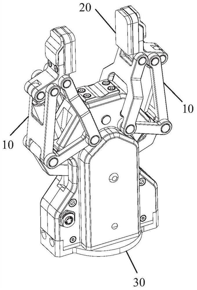
[0053] An embodiment of the present invention proposes a mechanical arm end effector, see figure 1 , the end effector of the robotic arm includes:
[0054] detection circuit;
[0055] at least two jaws 10;
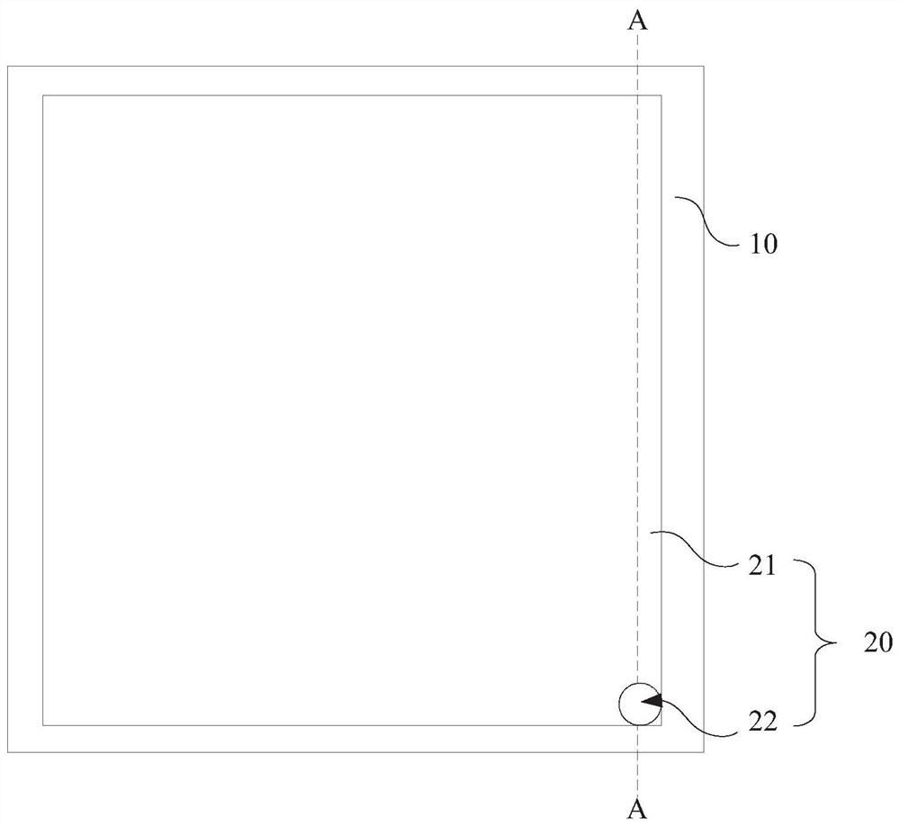
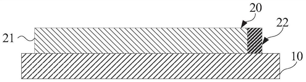
[0056] At least two electrodes 20, the at least two electrodes 20 are respectively arranged inside the at least two jaws 10, and the at least two electrodes 20 are respectively electrically connected to the detection circuit;
[0057] Among them, the electrode 20 can form a capacitance with an adjacent conductor, and transmit the electrical signal used to represent the capacitance or its variation to the detection circuit, and the detection circuit is used to convert the electrical signal representing the capacitance or its variation into a capacitance value or its value. A variable electrical signal.
[0058]The main function of the end effector of the mechanical arm proposed in the embodiment of the present invention is to grab an item, which mainly includes at least ...
Embodiment 2
[0067] The end effector of the robotic arm proposed by the embodiment of the present invention further includes: a mounting base 30 on which at least two jaws 10 are disposed, and the mounting base 30 is used for connecting with the end of the mechanical arm. In this embodiment, the main function of the mounting base 30 is to install at least two jaws 10 and fix the at least two jaws 10 to the end of the mechanical arm, so as to drive the at least two jaws 10 to move through the end of the mechanical arm. The specific structure of the mounting seat 30 can be designed according to the actual situation, which is not limited in this embodiment, as long as it can realize the above two functions.
[0068] Specifically, after the mounting base 30 is fixed on the end of the mechanical arm, the mechanical arm drives at least two jaws 10 to move to the object to be grasped, and then the at least two jaws 10 clamp the object to be grasped. After grabbing the item, the mechanical arm dri...
Embodiment 3
[0072] The end effector of the robotic arm proposed by the embodiment of the present invention further includes: at least two pressure sensors, and the at least two pressure sensors are respectively arranged inside at least two jaws 10 . In this embodiment, when at least two jaws 10 are clamping the object to be grasped, if the distance between one of the jaws 10 and the conductor to be grasped is different from the distance between the other jaws 10 and the conductor, it is also possible to continue to control the The gripper 10 moves until it contacts the conductor to be grasped. When the gripper 10 contacts the conductor to be grasped, the pressure sensor installed inside the gripper 10 will detect this signal and send this signal to the control The controller controls the jaw 10 to stop moving according to the signal. Then, after other clamping jaws 10 are also in contact with the conductor to be grasped, the clamping jaw 10 is controlled to continue to move towards the co...
PUM
 Abstract
Description
Claims
Application Information
 - R&D
- Intellectual Property
- Life Sciences
- Materials
- Tech Scout
- Unparalleled Data Quality
- Higher Quality Content
- 60% Fewer Hallucinations
Browse by: Latest US Patents, China's latest patents, Technical Efficacy Thesaurus, Application Domain, Technology Topic, Popular Technical Reports.
© 2025 PatSnap. All rights reserved.Legal|Privacy policy|Modern Slavery Act Transparency Statement|Sitemap|About US| Contact US: help@patsnap.com