Corner pressing device for sanitation brush

A technology of a pressing device and a sanitation brush, which is applied in the field of sanitation brushes, and can solve problems such as retaining springs, unfavorable batch production, troublesome adjustments, etc.

Pending Publication Date: 2021-04-09
湖南盛瑞环保科技有限公司
View PDF0 Cites 0 Cited by
  • Summary
  • Abstract
  • Description
  • Claims
  • Application Information

AI Technical Summary

Problems solved by technology

However, this patent has certain technical defects, such as complex structure, high production cost, which is not conducive to mass production, and the internal spring is prone to elastic fatigue or circlip phenomenon, which makes the pressing device unadjustable, and it is very troublesome to adjust. , resulting in a waste of time

Method used


Image

  • Corner pressing device for sanitation brush
  • Corner pressing device for sanitation brush
  • Corner pressing device for sanitation brush

Examples


Embodiment 1

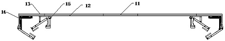
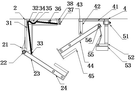
[0024] see figure 1 and figure 2 , an edge and corner pressing device for sanitation brushes, comprising a work frame plate 11, two ends of the work frame plate 11 are provided with a pressing end frame 12, and a side edge frame 13 is provided at the pressing end frame 12 , the inner end positions of the side frame 13 are respectively provided with an external compression frame 14 and a built-in compression frame 15, the main body of the external compression frame 14 is an L-shaped frame 2, and the L-shaped frame 2 A mounting block 21 is installed at the bottom end, and a clamping frame plate 23 is installed on the installation block 21 through the steering shaft 22 . The inner cavity of the profile frame 2 is provided with a transmission cavity 31, the inner cavity of the transmission cavity 31 is provided with a bending support rod 32, and the bending shape of the bending support rod 32 matches the structural shape of the transmission cavity 31, so The upper edge of the t...

Embodiment 2

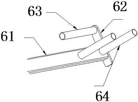
[0028] see image 3 , this embodiment is a further optimization of the first embodiment. On this basis, the first clamping device 24 and the second clamping device 45 are both provided with a mounting substrate 61, and a vertical frame is provided on the mounting substrate 61 Plate 62, the mounting base plate 61 and the vertical frame plate 62 are arranged at right angles, the inner plane of the mounting base plate 61 is provided with a first-level compression column 64, and the vertical frame plate 62 is provided with a second-level compression column 63 , the secondary pressing column 63 is parallel to the mounting substrate 61 and is perpendicular to the primary pressing column 64 . The secondary pressing column 63 is provided with one and is designed near the turning side of the mounting base plate 61 , and the primary pressing column 64 is arranged near the vertical shelf plate 62 . For the docking method of the first clamping device 24 and the second clamping device 45 ...


PUM


Abstract

The invention relates to the technical field of sanitation brushes, in particular to a corner pressing device for a sanitation brush, which comprises an operation frame plate, pressing end frames are arranged at two ends of the operation frame plate, side edge frames are arranged at the pressing end frames, an external pressing frame and an internal pressing frame are respectively arranged at the inner ends of the side edge frames, and a main body of the external pressing frame is an L-shaped frame, a mounting block is mounted at the bottom end of the L-shaped frame, a clamping frame plate is mounted on the mounting block through a steering shaft, a first clamping instrument is mounted at the plate face end of the clamping frame plate, a built-in pressing frame body is a built-in pressing frame, a top plate is arranged at the top of the built-in pressing frame, an upper edge supporting frame is mounted at the outer end of the top plate, and a pressing rotating shaft is mounted, and an upper pressing plate is arranged on the pressing rotating shaft, a second clamping instrument is installed at the outer end of the upper pressing plate, and the second clamping instrument is matched with the first clamping instrument. A synchronous and mutually-reverse operation mode is adopted, and the stability degree of corner pressing for the environmental sanitation brush is improved.

Description

technical field [0001] The invention relates to the technical field of sanitation brushes, in particular to a corner pressing device for sanitation brushes. Background technique [0002] The disc brush or steel wire disc brush installed in the municipal sanitation vehicle for street cleaning is the most representative type of sanitation brush. Brushes, sweeper brushes, square road sweeping brushes, round branch road sweeping brushes, sewage treatment brushes, floor washing machine brushes, computer car washing machine brushes, etc. [0003] The name of the invention is the Chinese patent. It is a corner pressing device for sanitation brushes, including a base, the top of the base is fixedly connected with a worktable, and the top of the base is fixedly connected with two symmetrical A support column is fixedly connected between the tops of the two support columns, a support plate is fixedly connected to the bottom of the support plate, and a ring seat is fixedly connected t...

Claims


Application Information

Patent Timeline
IPC IPC(8): E01H1/05
CPCE01H1/05
Inventor 匡小勇
Owner 湖南盛瑞环保科技有限公司
Why Eureka
Try Eureka