Scenic area complex terrain steel structure installation method

A technology of complex terrain and installation method, applied in the direction of building structure, construction, building materials processing, etc., can solve the problems that the erection height should not exceed 30 meters, there is no level ground, and vehicles cannot directly access the construction site, etc., to achieve a solution The Effects of Operating Platform Issues

Active Publication Date: 2018-12-28
上海宝冶建筑装饰有限公司 +1
View PDF5 Cites 0 Cited by
  • Summary
  • Abstract
  • Description
  • Claims
  • Application Information

AI Technical Summary

Problems solved by technology

At present, fastener-type scaffolding is generally used for high-altitude installation of steel structures, which requires a lot of manpower and material resources, and the installation period is long and the efficiency is very low; The height of the one-piece full hall support frame should not exceed 30 meters, but the height of current aerial work projects often exceeds 30 meters, which cannot meet the requirements
[0003] In addition, when constructing on cliffs similar to scenic spots, the terrain is complex, the height difference of the site is huge, there is no complete leveling site, vehicles cannot directly access the construction site, large machinery and equipment cannot be used on site, material transportation and supporting tire frames Setting up is a problem

Method used


Image

  • Scenic area complex terrain steel structure installation method
  • Scenic area complex terrain steel structure installation method

Examples


Embodiment Construction

[0019] The present invention will be further described below in conjunction with the accompanying drawings and specific embodiments, so that those skilled in the art can better understand the present invention and implement it, but the examples given are not intended to limit the present invention.

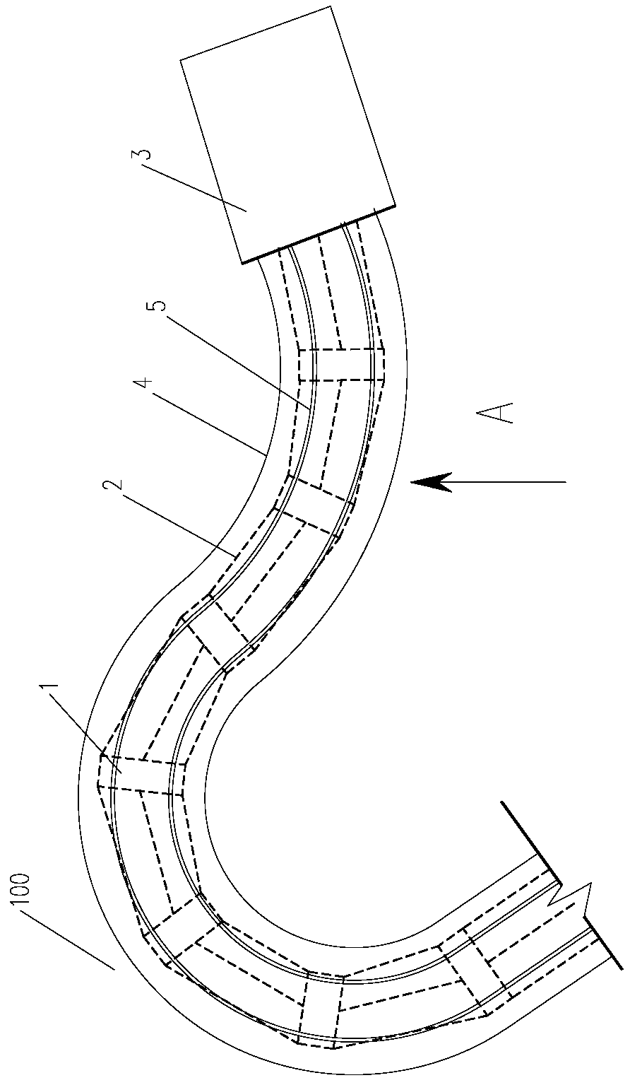
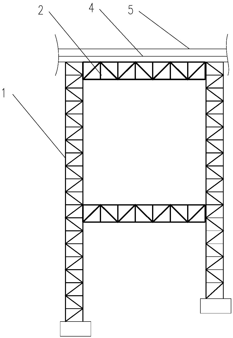
[0020] A method for installing steel structures in complex terrain in scenic spots, such as figure 1 and figure 2 shown, including the following steps:

[0021] A: Decompose the steel structure and supporting frame to be installed into multiple parts, build a cableway between the ground and the unloading platform 3, and transport the multiple parts to the unloading platform 3 through the cableway , the weight of each component is less than the load of the cableway; for example, the steel pipe column in the steel structure is segmented according to the lifting weight of the cableway (1 ton), and the box girder in the steel structure is decomposed into less than 1 ton The steel p...


PUM


Abstract

The invention provides a scenic area complex terrain steel structure installation method which includes the steps: A dividing a steel structure to be installed and a supporting bed jig to be installedinto a plurality of components, and transporting the components to a discharging platform through a ropeway; B erecting the supporting bed jig on the construction site; C taking the supporting bed jig as a transportation channel to transport the components of the steel structure to positions to be installed; D taking the supporting bed jig as an operation platform to assembling the steel structure. The scenic area complex terrain steel structure installation method overcomes the problems of difficulty of transportation of materials and erection of the supporting bed jig, a fastener-type scaffold is omitted, the erected supporting bed jig serves as the installation operation platform and the transportation channel of the steel structure, the steel structure is transported in a complex terrain, and the operation platform for installing the steel structure is achieved without large machinery operation by the method.

Description

technical field [0001] The invention relates to the technical field of building construction, in particular to a method for installing a steel structure in the complex terrain of a scenic spot. Background technique [0002] With the development of the economy, various types of steel structure buildings emerge in an endless stream in our country, and the height, span and complexity gradually increase. When a complex steel structure project is installed at high altitude, it needs to be installed in sections and blocks. When the entire structural system has not yet been formed, a support system and a construction operation platform are needed to bear the weight of the steel structure. This temporary construction measure is to support the tire frame. . At present, fastener-type scaffolding is generally used for high-altitude installation of steel structures, which requires a lot of manpower and material resources, and the installation period is long and the efficiency is very l...

Claims


Application Information

Patent Timeline
Patent Type & Authority Applications(China)
IPC IPC(8): E04G21/14
CPCE04G21/14
Inventor 张通王会玲陈亮边树旺
Owner 上海宝冶建筑装饰有限公司
Why Eureka
Try Eureka