Supercharge Your Innovation With Domain-Expert AI Agents!

Main reducer driving and driven gear backlash automatic adjustment detection device

A tooth backlash and automatic adjustment technology, applied in the direction of measuring devices, mechanical backlash measurement, mechanical measuring devices, etc., can solve the problems of poor consistency of adjustment and detection, high labor intensity, and inability to realize automatic operation, so as to reduce labor intensity, Save manpower and improve process consistency

Pending Publication Date: 2021-04-09
SHANDONG LINGONG CONSTR MACHINERY
View PDF1 Cites 0 Cited by
  • Summary
  • Abstract
  • Description
  • Claims
  • Application Information

AI Technical Summary

Problems solved by technology

At present, when assembling the main reducer, most main engine factories generally use manual adjustment of the side clearance of the main and slave bevel gears, manual detection of the tooth side clearance, and manual judgment and identification of the meshing spots based on experience. The operation is labor-intensive and the consistency of adjustment and detection is poor. Automate operation
[0003] In the prior art, for example, the patent application number CN201410818076.5 discloses a system for adjusting the rotational torque of the main reducer bearing and the auxiliary tooth side clearance of the active and passive gears. However, the patent does not provide a solution for the automatic detection of the master-slave bevel clearance and the automatic identification and judgment of the spot marks after gear meshing

Method used


Image

  • Main reducer driving and driven gear backlash automatic adjustment detection device
  • Main reducer driving and driven gear backlash automatic adjustment detection device
  • Main reducer driving and driven gear backlash automatic adjustment detection device

Examples


Embodiment 1

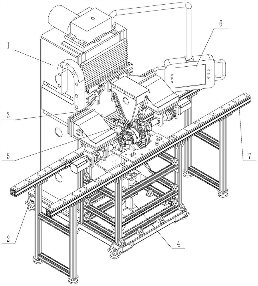
[0030] Such as figure 1 As shown in the figure, an automatic adjustment and detection device for the tooth side clearance of the driving and driven gears of the main reducer, including a lifting body 1, an installation base 2, a tooth side clearance adjustment measurement device 3, a lifting rotation measurement device 4, and a meshing mark photographing analysis system 5 , the operation panel 6 and the conveying line 7, the lifting body 1 is respectively connected with the installation base 2, the tooth side clearance adjustment measurement device 3, the lifting rotation measurement device 4 and the operation panel 6, and the meshing mark photographing analysis system 5 is installed on the tooth side On the gap adjustment measuring device 3 , the installation base 2 is respectively connected with the lifting and rotating measuring device 4 and the conveying line 7 .

Embodiment 2

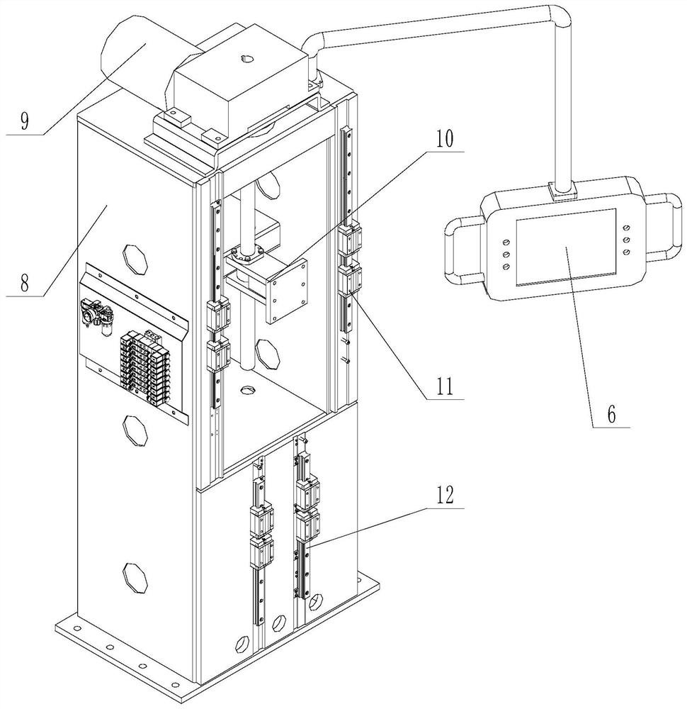
[0032] Such as figure 2 As shown, an automatic adjustment and detection device for the tooth side clearance of the main and driven gears of the main reducer, the lifting body 1 includes a mechanical body 8, a lifting motor 9, a screw module 10, an upper slider module 11 and a lower slider Module 12, the lifting motor 9 is installed on the upper end of the machine body 8, the output end of the lifting motor 9 is connected to the screw module 10, and the upper slider module 11 and the lower slider module 12 are installed on the mechanical One side of body 8. The operation panel 6 is connected to the mechanical body 8 . The upper slider module 11 and the lower slider module 12 both have a slider+guide rail structure, the guide rail is installed on the mechanical body 8, and the slider can slide up and down and be installed on the guide rail.

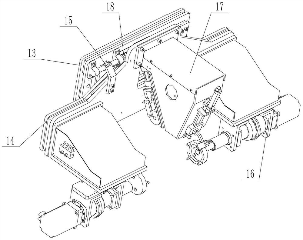
[0033] Such as image 3 As shown, the gear backlash adjustment and measurement device 3 includes a main mounting plate 13, an adjustme...


PUM


Abstract

The invention discloses a main reducer driving and driven gear backlash automatic adjustment detection device and belongs to the technical field of engineering machinery. With the main reducer driving and driven gear backlash automatic adjustment detection device adopted, the defects of large operation labor intensity and poor adjusting and detecting consistency due to traditional manual adjustment of the backlash of a driving spiral bevel gear and a driven spiral bevel gear are overcome in the prior art. The main structure of the device comprises an elevator body, a mounting base, a gear backlash adjusting and measuring device, a lifting and rotating measuring device and a conveying line; the elevator body is connected with the mounting base, the gear backlash adjusting and measuring device and the lifting and rotating measuring device; the mounting base is connected with the lifting and rotating measuring device and the conveying line. The device is mainly used for engineering machinery.

Description

Technical field: [0001] The invention belongs to the technical field of construction machinery, and in particular relates to an automatic adjustment and detection device for the tooth side clearance of the main and driven gears of the main reducer. Background technique: [0002] With the rapid development of the construction machinery industry, people's requirements for the quality of loaders are constantly improving, especially for the main reducer of the drive axle. The quality of the main subtraction assembly. At present, when assembling the main reducer, most main engine factories generally use manual adjustment of the side clearance of the main and slave bevel gears, manual detection of the tooth side clearance, and manual judgment and identification of the meshing spots based on experience. The operation is labor-intensive and the consistency of adjustment and detection is poor. Automate operations. [0003] In the prior art, for example, the patent application numbe...

Claims


Application Information

Patent Timeline
IPC IPC(8): G01B5/16G01B5/00G01M13/021G01M13/025B66F7/16B66F7/28F16H57/12G01D21/02
CPCB66F7/16B66F7/28F16H57/12F16H2057/125G01B5/0002G01B5/166G01D21/02G01M13/021G01M13/025
Inventor 陈宝刚郭恒博刘成江王永俊张连敬闵凡阁张小娜
Owner SHANDONG LINGONG CONSTR MACHINERY
Features
  • R&D
  • Intellectual Property
  • Life Sciences
  • Materials
  • Tech Scout
  • Unparalleled Data Quality
  • Higher Quality Content
  • 60% Fewer Hallucinations
Learn More