LED appearance detection machine and manufacturing method

An inspection machine and appearance technology, which is applied to measuring devices, optical testing flaws/defects, instruments, etc., can solve the problems of increasing the difficulty of image analysis for LED appearance inspection, increasing the amount of image analysis, and the interference of lighting effects of light-emitting components.

Active Publication Date: 2021-04-09
YANCHENG DONGSHAN PRECISION MANUFACTURING CO LTD
View PDF6 Cites 1 Cited by
  • Summary
  • Abstract
  • Description
  • Claims
  • Application Information

AI Technical Summary

Problems solved by technology

[0002] LED (Light Emitting Diode) is a commonly used light-emitting device. It emits energy through the recombination of electrons and holes. It is widely used in the field of lighting. The light-emitting components in LED are encapsulated in the shell of injection molding materials. In mass production, There are differences in the position of the light-emitting components in the injection-molded housing in the LED, and the injection-molded housing will also affect the shape of the injection-molded housing during the thermal curing process of the LED light-emitting components, which interferes with the lighting effect of the light-emitting components.
[0003] The protruding pins in the LED will make it in different postures during the transfer process. At the same time, the LED is in a fixed position during the photographing process, and the photographed picture can only obtain a single angle of view of the LED, so that the LED images reflected in the photograph are in different positions. Under different postures and viewing angles, it increases the difficulty of analyzing the LED appearance detection image, and limits the coverage of the overall LED appearance detection, which in turn affects the detection effect of the LED appearance
[0004] There are also some technical solutions about LED appearance detection in the prior art. For example, a Chinese patent with application number 2014107411156 discloses a LED appearance inspection machine, including a feeding unit that drives the LED semi-finished material belt to move; it is used for LED semi-finished products CCD detection unit for quality inspection; a cutting unit that cuts the LED semi-finished material tape after the feeding unit along the feeding direction of the feeding unit; a controller for controlling the cooperative work of the above components; there are four CCD detection units, along the feeding unit The feeding direction is arranged in sequence, the CCD detection unit includes a camera, and the camera is located above the feeding unit; the feeding unit, the cutting unit and the camera are respectively electrically connected to the controller; this technical solution has the advantages of saving products, reducing waste, fast detection speed, accuracy and reliability It has the advantages of high performance and labor cost saving; however, this technical solution does not solve the problem that when LEDs are photographed and detected, the LEDs are in different postures and angles of view, so that there are initial differences between the acquired images, which increases the required time for the images. The amount of analysis, and limits the detection effect on the overall appearance of the LED

Method used


Image

  • LED appearance detection machine and manufacturing method
  • LED appearance detection machine and manufacturing method
  • LED appearance detection machine and manufacturing method

Examples


Embodiment approach

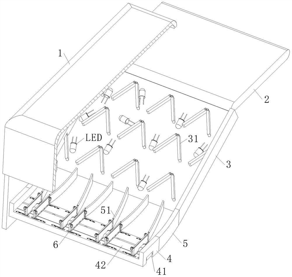
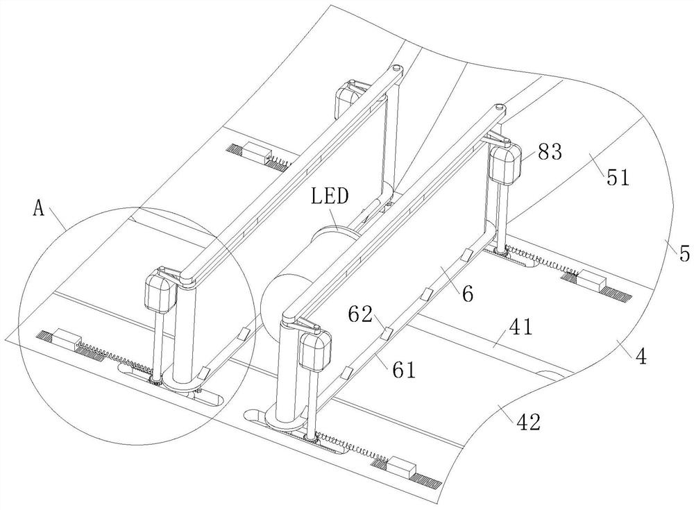
[0032] As an embodiment of the present invention, the two ends of the orientation plate 51 are slidingly installed on the arc-shaped disc 5, and the orientation plate 51 is hingedly connected with the traction roller belt 6; the bottom of the traction roller belt 6 is also provided with a positioning Slider 7, positioning slider 7 is installed in the chute 43 on the detection disc 4; when working, the running traction belt 42 drives the LED to rotate, which will make the LED move to one side of the traction roller belt 6, and on the traction roller The surface of the traction belt 42 between the belts 6 produces reciprocating rolling, which makes the position of the LED in the image taken by the detection camera different, and is not conducive to the appearance detection of the LEDs of different sizes by the traction roller belt 6; The slide block 7 cooperates with the directional plate 51 hingedly connected to the arc-shaped disc 5. When detecting LEDs of different sizes, by a...


PUM


Abstract

The invention belongs to the technical field of LED appearance detection and relates to an LED appearance detection machine and a manufacturing method. The LED appearance detection machine comprises a shell, a material belt, a guide plate and a controller; due to the fact that protruding pins in LEDs enable the LEDs to be in different postures in a transferring process, meanwhile, the LEDs in a photographing process are located at fixed positions, a photographed picture can only obtain the condition of a single view angle of the LEDs, LED images reflected by photographing are located in different postures and view angles respectively, the coverage rate of overall appearance detection of the LED is limited, and the detection effect on the appearance of the LEDs is influenced; and therefore, the postured of the LEDs are adjusted through the guide plate of the LED appearance detection machine of the invention; a traction belt in a detection disc is adopted, so that a detection camera can obtain a multi-view photo of the single LED, the integrity of appearance detection of the single LED is improved, the distribution difference between the LEDs in a picture shot by the camera is reduced, the processing amount of image analysis is reduced, and the detection accuracy is improved. Therefore, the operation effect of the LED appearance detection machine is improved.

Description

technical field [0001] The invention relates to the technical field of LED appearance inspection, in particular to an LED appearance inspection machine and a manufacturing method. Background technique [0002] LED (Light Emitting Diode) is a commonly used light-emitting device. It emits energy through the recombination of electrons and holes. It is widely used in the field of lighting. The light-emitting components in LED are encapsulated in the shell of injection molding materials. In mass production, There are differences in the positions of the light-emitting components in the injection-molded casing in the LED, and the injection-molded casing will also affect the shape of the injection-molded casing during the thermal curing process of the LED light-emitting component, which interferes with the lighting effect of the light-emitting component. [0003] The protruding pins in the LED will make it in different postures during the transfer process. At the same time, the LED ...

Claims


Application Information

Patent Timeline
Patent Type & Authority Applications(China)
IPC IPC(8): G01B11/24G01N21/84G01N21/95B29C69/00
CPCG01B11/24G01N21/84G01N21/95B29C69/00
Inventor 梁新波朱伟忠
Owner YANCHENG DONGSHAN PRECISION MANUFACTURING CO LTD
Why Eureka
Try Eureka