Soil constitutive simulation calculation method and system

A technology of analog calculation and constitutive model, applied in special data processing applications, instruments, electrical digital data processing, etc., can solve problems such as inability to accurately calculate soil constitutive

Pending Publication Date: 2021-04-09
CHINA ELECTRIC POWER RES INST +2
View PDF0 Cites 0 Cited by
  • Summary
  • Abstract
  • Description
  • Claims
  • Application Information

AI Technical Summary

Problems solved by technology

However, most studies consider the foundation and the superstructure separately. The foundation is regarded as absolute rigidity, and the bottom of the superstructure is used as a fixed end for research. However, the foundation of the electrical equipment will inevitably be deformed during the earthquake. The vibration of the superstructure has an impact, and this kind of influence on the natural vibration characteristics, stress and displacement of the superstructure has not been studied, which leads to the inability of the existing methods to accurately calculate the soil constitutive simulation

Method used


Image

  • Soil constitutive simulation calculation method and system
  • Soil constitutive simulation calculation method and system
  • Soil constitutive simulation calculation method and system

Examples


Embodiment 1

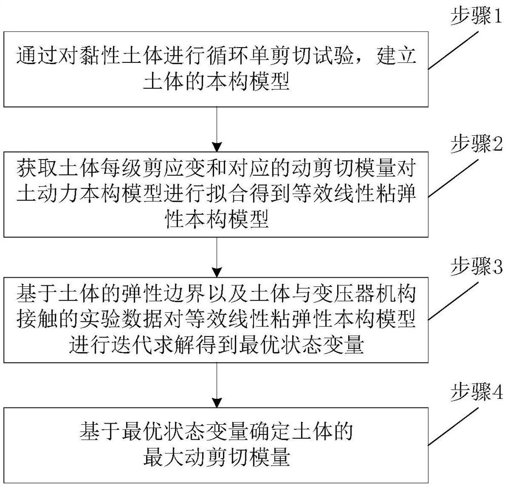
[0056] A schematic flow chart of a soil constitutive simulation calculation method provided by the present invention is as follows: figure 1 shown, including:

[0057] Step 1: Establish a constitutive model of the soil by performing a cyclic single shear test on the cohesive soil;

[0058] Step 2: Obtain the shear strain of each level of the soil and the corresponding dynamic shear modulus to fit the soil dynamic constitutive model to obtain the equivalent linear viscoelastic constitutive model;

[0059] Step 3: based on the elastic boundary of the soil and the experimental data of the contact between the soil and the transformer mechanism, iteratively solve the equivalent linear viscoelastic constitutive model to obtain the optimal state variable;

[0060] Step 4: Determine the maximum dynamic shear modulus of the soil based on the optimal state variables.

[0061] Step 1 specifically includes:

[0062] The present invention provides a soil constitutive simulation calculat...

Embodiment 2

[0088] Based on the same inventive idea, the present invention also provides a soil constitutive simulation calculation system.

[0089] The basic structure of the system is as Image 6 As shown, including: constitutive model module, viscoelastic model module, iterative calculation module and maximum dynamic shear modulus module;

[0090] The constitutive model module is used to establish the constitutive model of the soil by performing a cyclic single shear test on the cohesive soil;

[0091] The viscoelastic model module is used to obtain the shear strain of each level of the soil and the corresponding dynamic shear modulus to fit the soil dynamic constitutive model to obtain an equivalent linear viscoelastic constitutive model;

[0092] The iterative calculation module is used to iteratively solve the equivalent linear viscoelastic constitutive model based on the elastic boundary of the soil and the experimental data of the contact between the soil and the transformer mech...


PUM


Abstract

The invention provides a soil constitutive simulation calculation method and system, and the method comprises the steps: building a constitutive model of a soil body through carrying out cyclic single shear test on the cohesive soil body; obtaining each level of shearing strain of the soil body and a corresponding dynamic shearing modulus, and fitting the soil dynamic constitutive model to obtain an equivalent linear viscoelasticity constitutive model; iteratively solving the equivalent linear viscoelasticity constitutive model based on the elastic boundary of the soil body and the experimental data of the contact between the soil body and the transformer mechanism to obtain an optimal state variable; and determining the maximum dynamic shear modulus of the soil body based on the optimal state variable. According to the method, the influence of interaction between the soil body and the transformer is considered, the calculation model depends on test result parameter values, and the calculation reliability is high; and the influence of cohesive soil is considered, and the method is suitable for three-dimensional soil and structure models and is closer to engineering practice.

Description

technical field [0001] The invention belongs to the technical field of power grid disaster prevention and mitigation, and in particular relates to a soil constitutive simulation calculation method and system. Background technique [0002] In the traditional calculation and analysis of structural dynamics, for structures built on soil or rocks, the foundation of the site is often assumed to be rigid, that is, only the interaction between the structure and the foundation is considered, and the Its deformation coordination problem. In fact, due to the non-absolute rigidity of foundation materials, even compared with structural materials, they have strong nonlinear deformation properties. During the process of dynamic loading, there is both force interaction and There are mutual constraints of deformation, which in turn cause the mutual transmission and exchange of vibration energy, which makes the dynamic response of the actual structure different from the response calculated ...

Claims


Application Information

Patent Timeline
IPC IPC(8): G06F30/13
CPCG06F30/13G06F2119/14
Inventor 王海菠程永锋卢智成朱祝兵刘振林李圣林森孙宇晗张谦孟宪政高坡薛耀东章姝俊
Owner CHINA ELECTRIC POWER RES INST
Why Eureka
Try Eureka