Eureka AIR delivers breakthrough ideas for toughest innovation challenges, trusted by R&D personnel around the world.

Electrical control box

A technology for electrical control boxes and outer boxes, which is applied to electrical components, substation/switch layout details, substation/power distribution device shells, etc., and can solve problems such as poor heat dissipation, dead angle of heat dissipation, and loss of cooling effect of cooling gas

Pending Publication Date: 2021-04-09
天津砼天建筑工程有限公司
View PDF7 Cites 1 Cited by
  • Summary
  • Abstract
  • Description
  • Claims
  • Application Information

AI Technical Summary

Problems solved by technology

When only the exhaust fan is used for heat dissipation, there will usually be a heat dissipation dead angle inside the electrical control box. For most electrical control boxes, because there are many internal heating parts, the cooling gas will be heated to a high temperature quickly, so that the exhaust fan will be sent into the air. The cooling gas loses the cooling effect and the heat dissipation effect is poor

Method used


Image

  • Electrical control box
  • Electrical control box
  • Electrical control box

Examples


Embodiment Construction

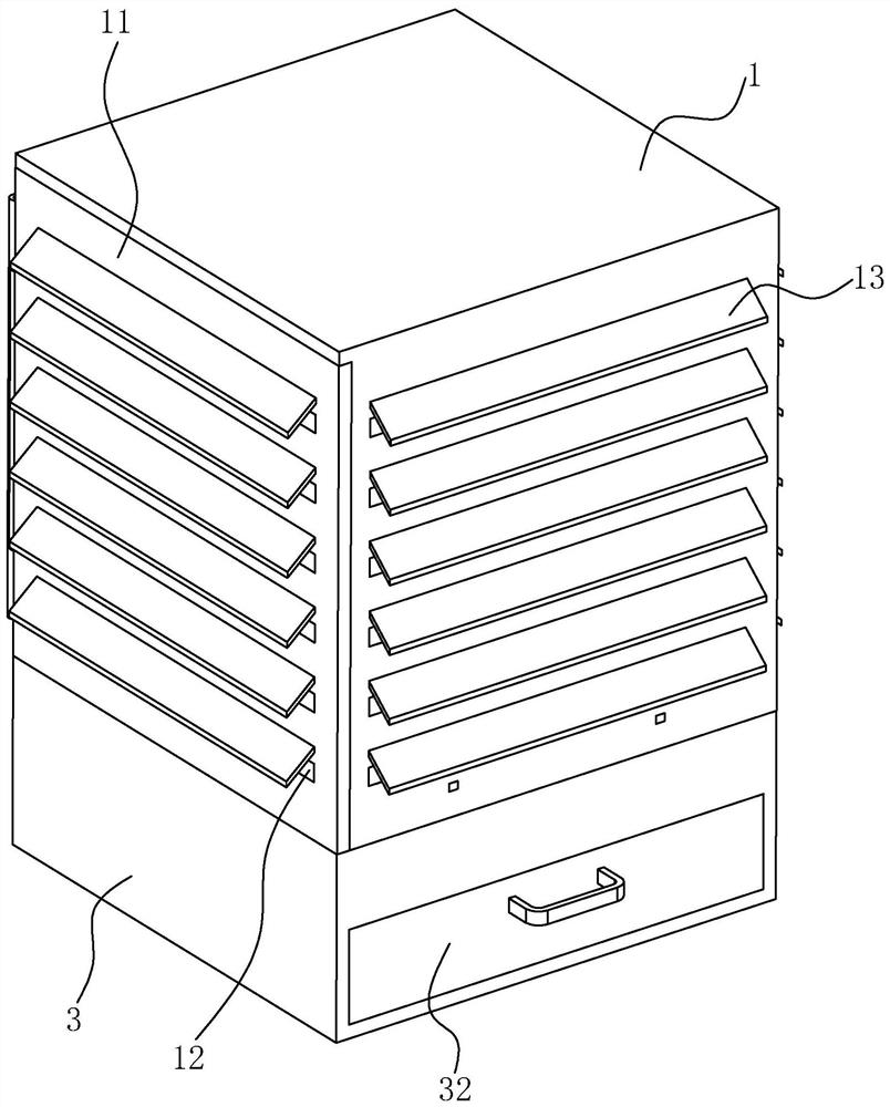
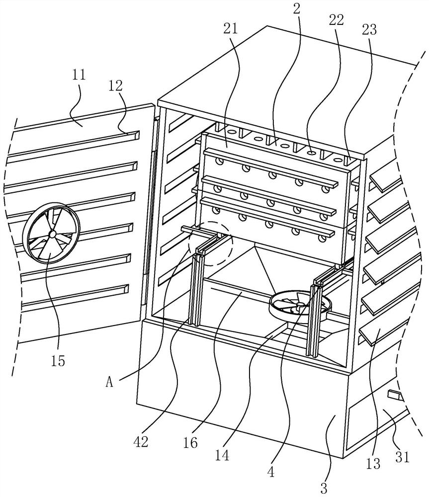
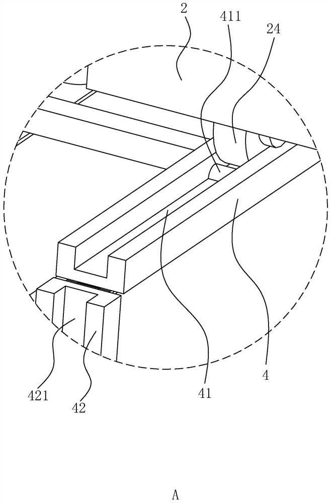
[0035] The following is attached Figure 1-4 The application is described in further detail.

[0036] The embodiment of the present application discloses an electrical control box. refer to figure 1 and figure 2 , an electrical control box includes an outer box 1 and an inner box 2, the inner box 2 is located in the outer box 1, the outer box 1 is fixedly provided with a fixing frame 4, and the inner box 2 is arranged on the fixing frame 4 , and is slidably connected with the fixed frame 4, and the bottom of the outer box body 1 is provided with a dust collection box 3.

[0037] refer to figure 1 and figure 2 , the outer box 1 and the inner box 2 are rectangular parallelepiped, there is a distance between the inner side of the outer box 1 and the outer side of the inner box 2, the top surface of the outer box 1 and the top surface of the inner box 2 Leave a distance between them, and leave a distance between the bottom surface of the outer box body 1 and the bottom sur...


PUM


Abstract

The invention relates to an electrical control box, which relates to the field of electrical equipment and comprises an outer box body and an inner box body arranged in the outer box body, wherein a distance is reserved between each side surface of the inner box body and each side surface of the outer box body, an outer box door is hinged to one side of the outer box body, an inner box door is hinged to one side, close to the outer box door, of the inner box body, The top face, the bottom face, each side face and the inner box door of the inner box body are each provided with a plurality of heat dissipation holes, each side face and the outer box door of the outer box body are each provided with a plurality of horizontal ventilation holes in the vertical direction, the sides, away from the inner box body, of the ventilation holes incline downwards, and heat dissipation fans are fixedly arranged on the top surface, the bottom surface, each side surface and the inner side of the outer box door of the outer box body. The electric control box has the effect of improving the heat dissipation effect of the electric control box.

Description

technical field [0001] The present application relates to the field of electrical equipment, in particular to an electrical control box. Background technique [0002] The control box is the power distribution equipment for power, lighting power distribution and motor control. At present, electrical components are installed in a closed or semi-closed metal cabinet in the electrical control box. When the internal electrical appliances work normally, a certain amount of heat will be generated and gathered inside the box. Overheating will easily cause damage to the electrical components. [0003] In order to dissipate the heat in the control box, the existing electric control box usually adopts the form of an exhaust fan to dissipate heat. When only the exhaust fan is used for heat dissipation, there will usually be a heat dissipation dead angle inside the electrical control box. For most electrical control boxes, because there are many internal heating parts, the cooling gas w...

Claims


Application Information

Patent Timeline
IPC IPC(8): H02B1/46H02B1/56H02B1/28
CPCH02B1/46H02B1/565H02B1/28
Inventor 李磊范国娜周军晓
Owner 天津砼天建筑工程有限公司
Why Eureka
Eureka Blog
Learn More