Intelligent shoe cabinet and control method thereof

A shoe cabinet and intelligent technology, which is applied to the cleaning of cabinets, wardrobes, boots and shoes, etc., can solve the problems of single function, poor daily experience and low user satisfaction of smart shoe cabinets, and achieve easy replacement, space utilization, design Simple and clever effects

Active Publication Date: 2021-04-13
ANHUI UNIVERSITY OF TECHNOLOGY
View PDF18 Cites 1 Cited by
  • Summary
  • Abstract
  • Description
  • Claims
  • Application Information

AI Technical Summary

Problems solved by technology

[0006] The purpose of the present invention is to solve the problems of single function of the existing intelligent shoe cabinet, inconvenient operation of taking and exchanging shoes, low user satisfaction and poor daily experience, and provides an intelligent shoe cabinet and its control method

Method used


Image

  • Intelligent shoe cabinet and control method thereof
  • Intelligent shoe cabinet and control method thereof
  • Intelligent shoe cabinet and control method thereof

Examples


Embodiment 1

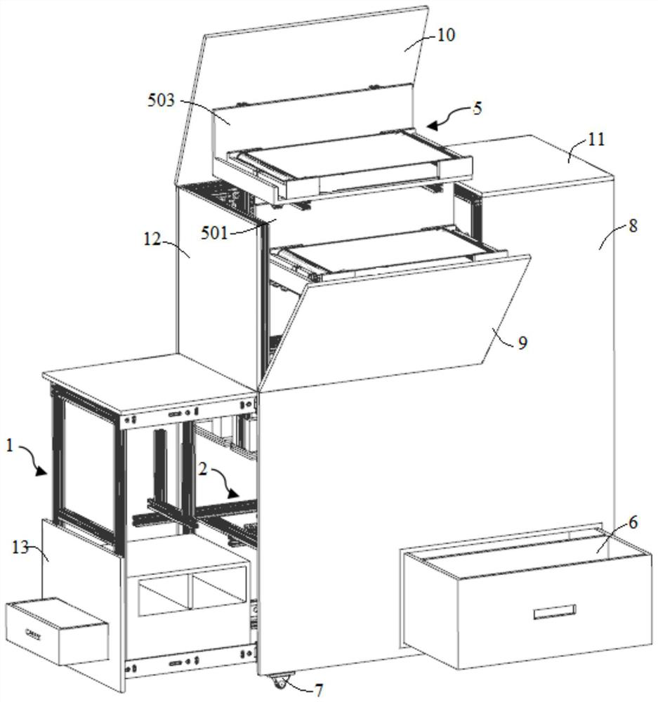
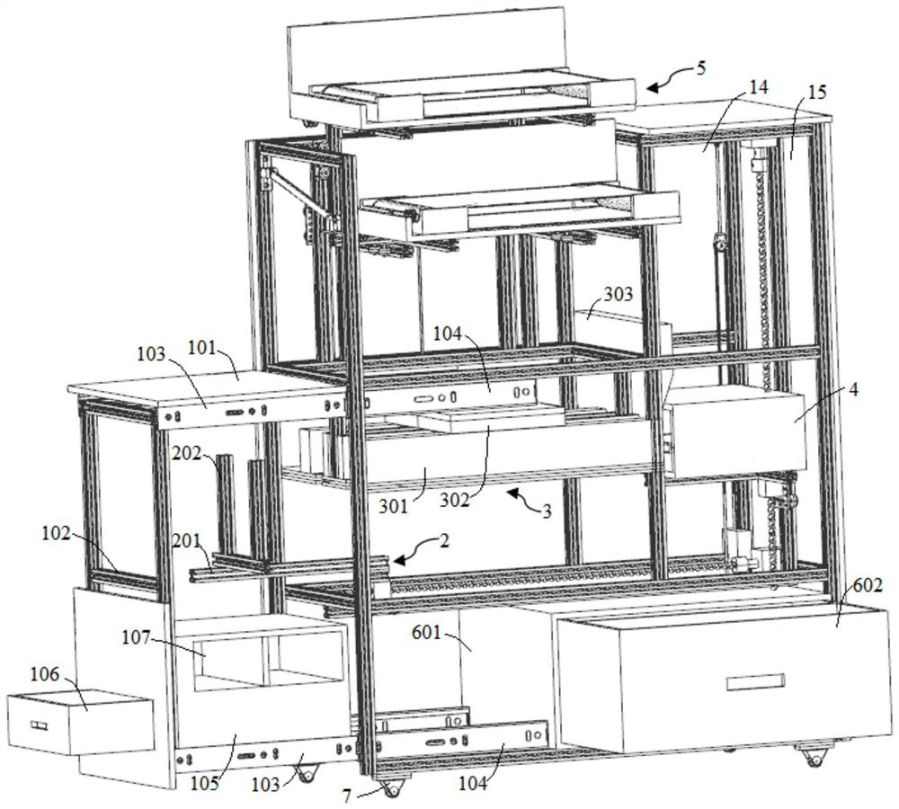
[0057] Such as figure 1 with figure 2 As shown, a kind of smart shoe cabinet of this embodiment ("up, down, left and right" involved in this embodiment are all according to figure 1 The view prevails), the shoe cabinet is fixed by multiple profiles to form an overall support frame, and its exterior is surrounded by various sealing plates to form a cabinet. The shoe cabinet includes a shoe changing unit 1, a cleaning unit 3 and a commonly used shoe storage unit 5, each unit is installed on the overall support frame of the shoe cabinet, and the shoe changing unit 1 can be slidably installed under one side of the overall support frame, so The cleaning unit 3 is correspondingly installed in the overall support frame, and the conveying mechanism 2 is correspondingly installed below the cleaning unit 3, and the shoes are transported in the cleaning unit 3 by the conveying mechanism 2; 1 side) is equipped with a lifting unit 4 that can move up and down, and a commonly used shoe st...

Embodiment 2

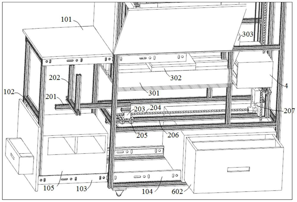
[0072] The control method of an intelligent shoe cabinet in this embodiment adopts the intelligent shoe cabinet described in Embodiment 1, and its actual operation can be controlled by a control unit, which is actually controlled by a single-chip microcomputer. The specific process is as follows: the user enters the door , trigger the gravity sensor installed on the outside of the shoe cabinet (this gravity sensor can also be hidden in the entry carpet), the gravity sensor sends the signal to the single-chip microcomputer for processing and analysis, and then the single-chip microcomputer controls the first drive motor 207 to drive the first The screw mandrel 204 rotates to make the first push rod 201 move to the left so that the support frame 102 of the shoe-changing stool is quickly released, so that the user can sit on the shoe-changing stool seat 101 and change shoes, and the shoes at the lower end of the shoe-changing stool support frame 102 can be changed. Take out the sh...


PUM


Abstract

The invention discloses an intelligent shoe cabinet and a control method thereof, and belongs to the technical field of smart home. The intelligent shoe cabinet comprises a shoe changing unit, a cleaning unit and a common shoe storage unit, all the units are installed on an overall supporting frame of the shoe cabinet, the shoe changing unit is installed below the shoe cabinet in a sliding mode, and a conveying mechanism is correspondingly installed on one side of the shoe changing unit and used for pushing out the shoe changing unit. The cleaning unit is installed above the conveying mechanism, a lifting unit capable of moving up and down is installed at the output end of the cleaning unit, and the common shoe storage unit capable of being lifted and unfolded is arranged above the cleaning unit. The shoe cabinet has the functions of scrubbing, sterilization and disinfection, shoe storage, lifting and unfolding for a user to select shoes and the like, the shoe taking and changing process is convenient, the changed shoes can be effectively stored at corresponding positions, and the shoe cabinet is user-friendly in structural design and high in practicability.

Description

technical field [0001] The invention belongs to the technical field of smart home, and more specifically relates to a smart shoe cabinet and a control method thereof. Background technique [0002] In people's daily life, the shoe cabinet is an indispensable piece of furniture for every family. However, with the emergence of the concept of smart furniture, the intelligentization, humanization and convenience of furniture electrical appliances have become new indicators for the rise of furniture at home and abroad. The development of smart home has made it overcome the disadvantages of simple ordinary home functions, but has developed into a series of products with strong practicability, intelligence and convenience, and smart shoe cabinets are just one of them. . [0003] The intelligent shoe cabinet refers to the requirement of intelligently completing the storage and retrieval of shoes by the mechanical device. Its appearance effectively solves the problem of tidying up sh...

Claims


Application Information

Patent Timeline
Patent Type & Authority Applications(China)
IPC IPC(8): A47B61/04A47B51/00A47B85/00A47L23/02A61L2/10A61L2/18A61L2/20A61L2/04A61L2/24A61L101/10
CPCA47B61/04A47B51/00A47B85/00A47L23/02A61L2/10A61L2/18A61L2/202A61L2/04A61L2/24A61L2202/14A61L2202/13
Inventor 陈傲王秀珍
Owner ANHUI UNIVERSITY OF TECHNOLOGY
Why Eureka
Try Eureka