Joint replacement surgery navigation system and method

A surgical navigation and joint replacement technology, applied in the medical field, can solve the problems of low registration accuracy, insufficient accurate positioning and quantitative analysis of lesion areas, long operation time, etc., and achieve the effect of improving safety

Active Publication Date: 2021-04-13
LONGWOOD VALLEY MEDICAL TECH CO LTD +1
View PDF8 Cites 19 Cited by
  • Summary
  • Abstract
  • Description
  • Claims
  • Application Information

AI Technical Summary

Problems solved by technology

The development of medical imaging technology (such as CT, MRI, etc., which can display the three-dimensional structure of complex structures) allows doctors to make a more complete and accurate assessment of the patient's condition than before, but these image features are not applicable to the operation process. Intraoperative doctors still mainly rely on two-dimensional X-ray images, and conduct local analysis and diagnosis based on clinical experience, which is far from enough for precise positioning and quantitative analysis of lesion areas. However, the existing preoperative three-dimensional model reconstructed from CT image data The registration accuracy between the operation and the patient's anatomy is low, the real-time performance is poor, and the operation time is long, which seriously affects the enthusiasm of doctors.
In addition, the traditional joint replacement surgery mainly relies on the doctor's surgical experience to place and implant the artificial joint through traditional surgical tools and instruments, which has low repeatability, poor accuracy, high risk of surgery, and postoperative complications. many

Method used


Image

  • Joint replacement surgery navigation system and method
  • Joint replacement surgery navigation system and method
  • Joint replacement surgery navigation system and method

Examples


Embodiment Construction

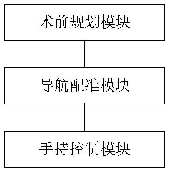
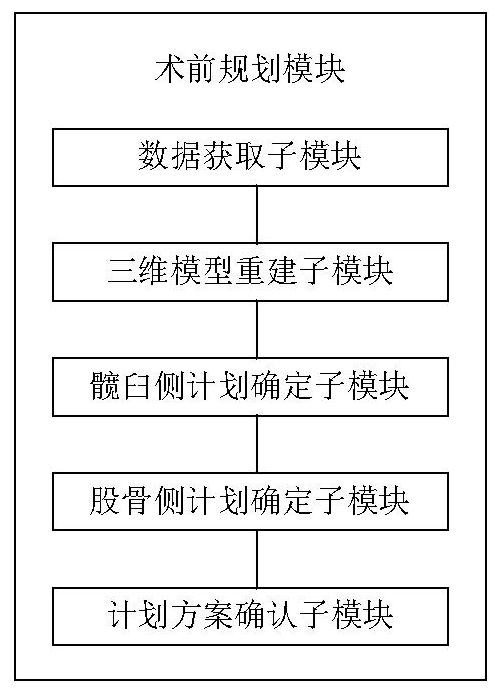
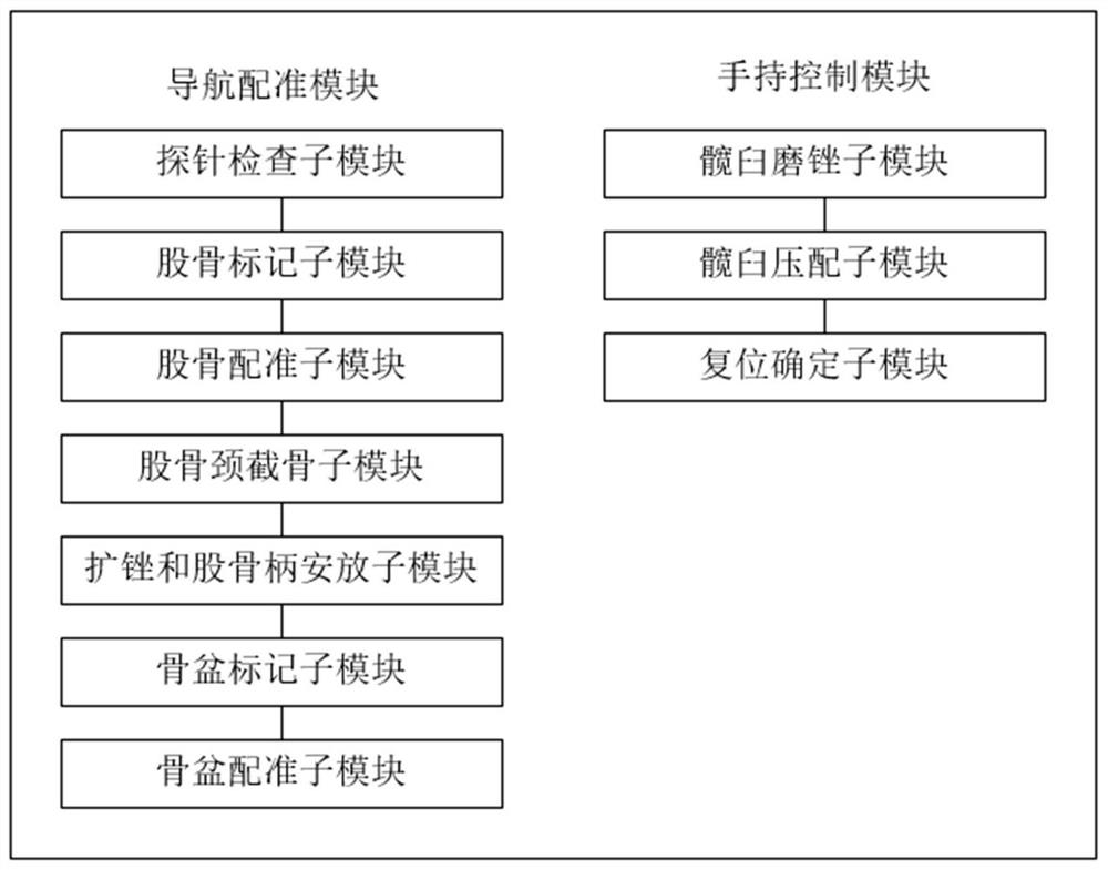
[0062] The specific embodiments of the present invention will be further described below in conjunction with the accompanying drawings. The following examples are only used to illustrate the technical solution of the present invention more clearly, but not to limit the protection scope of the present invention.

[0063] figure 1 It shows a navigation system for joint replacement surgery provided by an embodiment of the present invention, Figure 4 It is a schematic diagram of a navigation system for joint replacement surgery provided by an embodiment of the present invention, Figure 5 It is an interface diagram of a navigation system for joint replacement surgery provided by an embodiment of the present invention, Image 6 It is an interface diagram of another navigation system for joint replacement surgery provided by an embodiment of the present invention. Combine below figure 1 , Figure 4 , Figure 5 with Image 6 The navigation system for joint replacement surgery...


PUM


Abstract

The embodiment of the invention discloses a joint replacement surgery navigation system and method. The system comprises a preoperative planning module, and a navigation registration module, wherein the preoperative planning module is used for performing segmentation and reconstruction according to obtained hip joint medical image data to obtain a hip joint three-dimensional model, performing preoperative planning, and determining the placement position, size and angle of a prosthesis; and the navigation registration module is used for determining the spatial positions of the pelvis and the femur according to a pelvis reference frame and a femur reference frame, registering the hip joint three-dimensional model according to the spatial position relationship between an operation probe and the pelvis reference frame and the femur reference frame to obtain a hip joint solid model, and according to the hip joint solid model, controlling a surgical instrument for clamping the prosthesis to place the prosthesis in the hip joint. Through preoperative planning of information such as an operation approach and a prosthesis placement position, a spatial positioning method is used during an operation to track the operation instrument, navigation support is provided for a doctor while the operation accuracy is improved, and the operation is safer and more efficient.

Description

technical field [0001] The invention relates to the field of medical technology, in particular to a navigation system and method for joint replacement surgery. Background technique [0002] In recent years, hip replacement, as an effective clinical procedure for the treatment of severe hip pain, deformity, and dysfunction, has been widely carried out at home and abroad. The development of medical imaging technology (such as CT, MRI, etc., which can display the three-dimensional structure of complex structures) allows doctors to make a more complete and accurate assessment of the patient's condition than before, but these image features are not applicable to the operation process. Intraoperative doctors still mainly rely on two-dimensional X-ray images to conduct local analysis and diagnosis based on clinical experience, which is far from enough for precise positioning and quantitative analysis of lesion areas. However, the existing preoperative three-dimensional model recons...

Claims


Application Information

Patent Timeline
Patent Type & Authority Applications(China)
IPC IPC(8): A61B34/10A61B34/20A61F2/46
CPCA61B34/10A61B34/20A61F2/46A61B2034/105A61B2034/2055A61F2002/4633A61B17/1659A61F2002/4632A61B2034/2068A61B34/25A61B34/30A61B2034/252A61F2/32
Inventor 张逸凌刘星宇安奕成
Owner LONGWOOD VALLEY MEDICAL TECH CO LTD
Why Eureka
Try Eureka