Chamfering device for two ends of iron rod
A technology of chamfering corners and iron rods, which is applied to grinding drive devices, parts of grinding machine tools, and machine tools suitable for grinding workpiece edges, etc. It can solve problems such as high labor intensity, low work efficiency, and unsafety
- Summary
- Abstract
- Description
- Claims
- Application Information
AI Technical Summary
Problems solved by technology
Method used
Image

Examples
Embodiment 1
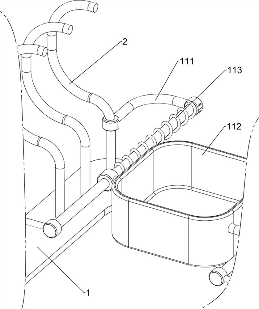
[0078] A device for chamfering both ends of an iron rod, such as figure 1 As shown, it includes a base 1, a first support frame 2, a second support frame 3, a grinding mechanism 4 and a rotation mechanism 5, and the left and right sides of the base 1 are provided with six first support frames 2 and six first support frames 2 A second support frame 3 is connected between the inner sides of the upper part, and the front part of the second support frame 3 is provided with a grinding mechanism 4 , and the second support frame 3 is provided with a rotation mechanism 5 , and the grinding mechanism 4 is connected with the rotation mechanism 5 .
[0079] When people need to chamfer the two ends of the iron rod, people fix the iron rod vertically in the grinding mechanism 4, then make the rotating mechanism 5 run, and make the grinding mechanism 4 partially run, and the rotating mechanism 5 makes the grinding mechanism 4 run completely , the grinding mechanism 4 grinds the two ends of ...
Embodiment 2
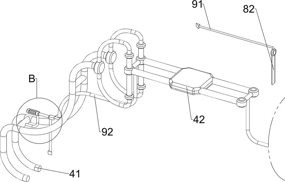
[0081] On the basis of Example 1, such as figure 2 with image 3 As shown, the grinding mechanism 4 includes a first slide rail 41, a third support frame 42, a first motor 43, a grinding block 44 and a first spring 45, the left side of the second support frame 3 left front part and the right side The front part of the right side of the second support frame 3 is provided with two first slide rails 41, between the two first slide rails 41 tops on the upper side and between the two first slide rails 41 bottoms on the downside. Connected with a third support frame 42, the middle part of the bottom side of the third support frame 42 on the upper side and the top side middle part of the third support frame 42 on the lower side are equipped with a first motor 43, and the output shafts of the first motor 43 on the upper and lower sides There are polishing blocks 44 on the top, the upper parts of the two first slide rails 41 on the upper side and the lower parts of the two first slid...
Embodiment 3
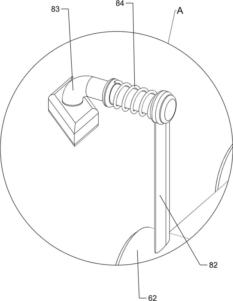
[0086] On the basis of Example 2, such as figure 1 , Figure 4 , Figure 5 , Image 6 , Figure 7 , Figure 8 , Figure 9 , Figure 10 with Figure 11 As shown, a fixing mechanism 6 is also included, and the fixing mechanism 6 includes a third slide rail 61, a clamp 62 and a second spring 63, and the second slide rails 51 on the left and right sides are slidingly provided with two third slide rails. 61, clamps 62 are slidably connected between the third slide rails 61 on the front and rear sides, the clamps 62 on the left and right sides cooperate with each other, and the second springs 63 are wound on the four third slide rails 61, and the inner sides of the second springs 63 It is connected with the clamp 62 , and the outer side of the second spring 63 is connected with the third slide rail 61 .
[0087] People manually make the clamp 62 slide outwards on the third slide rail 61, the second spring 63 changes from the initial state to the compressed state, then the ir...
PUM
 Abstract
Description
Claims
Application Information
 - R&D
- Intellectual Property
- Life Sciences
- Materials
- Tech Scout
- Unparalleled Data Quality
- Higher Quality Content
- 60% Fewer Hallucinations
Browse by: Latest US Patents, China's latest patents, Technical Efficacy Thesaurus, Application Domain, Technology Topic, Popular Technical Reports.
© 2025 PatSnap. All rights reserved.Legal|Privacy policy|Modern Slavery Act Transparency Statement|Sitemap|About US| Contact US: help@patsnap.com