Strip-shaped wood block grinding equipment

A wood block and bar-shaped technology, applied in the field of bar-shaped wood block grinding equipment, can solve the problems of low safety and low efficiency, and achieve the effect of improving safety and efficiency

Pending Publication Date: 2021-04-13
陈冬梅
View PDF7 Cites 3 Cited by
  • Summary
  • Abstract
  • Description
  • Claims
  • Application Information

AI Technical Summary

Problems solved by technology

[0005] In order to overcome the disadvantages of low safety and low efficiency of the old-fashioned grinding equipment, the technical problem of the present invention is to provide a strip-shaped wood grinding equipment with high safety and high efficiency

Method used


Image

  • Strip-shaped wood block grinding equipment
  • Strip-shaped wood block grinding equipment
  • Strip-shaped wood block grinding equipment

Examples


Embodiment 1

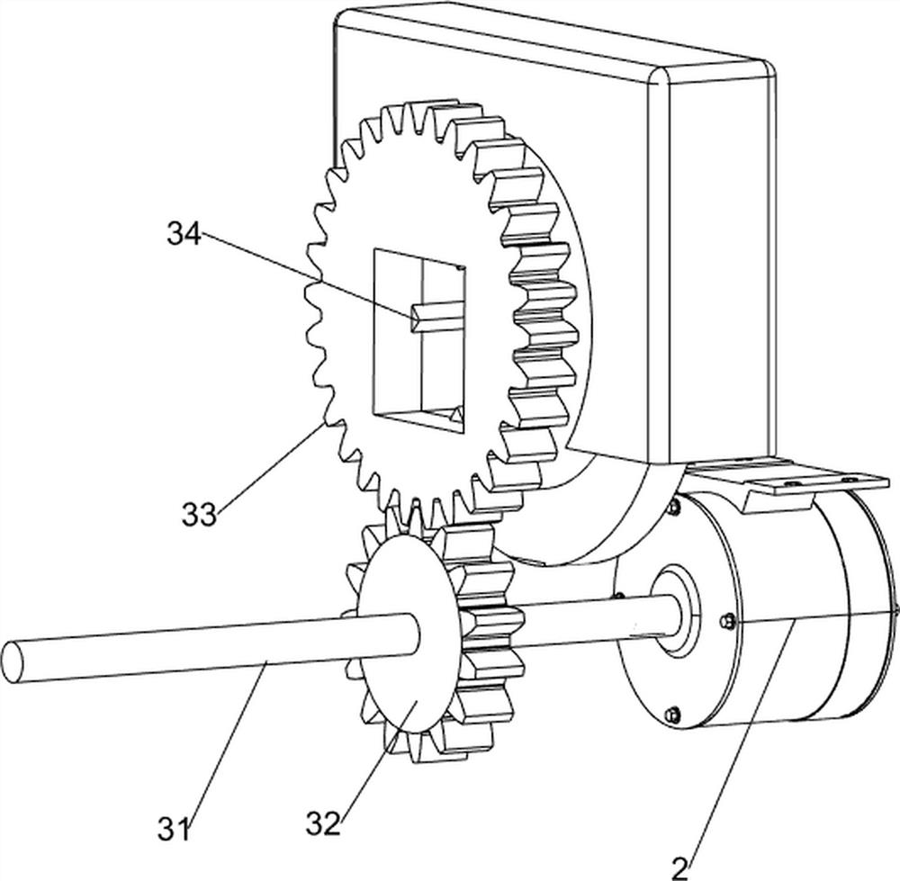
[0027] A kind of strip wood block grinding equipment, such as figure 1 , figure 2 , image 3 , Figure 4 , Figure 5 , Image 6 , Figure 7 and Figure 8 As shown, it includes a table 1, a motor 2, a first bearing seat 7, a second bearing seat 8, an abrasive mechanism 3, a pushing mechanism 4 and a feeding mechanism 5, and the motor 2 is installed on the lower side of the rear part of the table 1, and the upper middle part of the table 1 The rear side is provided with a first bearing seat 7, and the upper right side of the table 1 is provided with two second bearing seats 8, and the upper middle rear side of the table 1 is provided with an abrasive mechanism 3, and the abrasive mechanism 3 is connected with the output shaft of the motor 2, and the table 1 The upper middle part is provided with pusher mechanism 4, and pusher mechanism 4 is connected with the output shaft of motor 2, and table 1 left upper side is provided with feeder mechanism 5, and feeder mechanism 5 c...

Embodiment 2

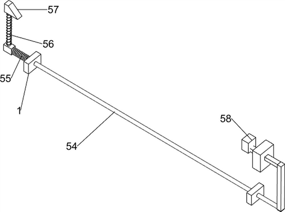
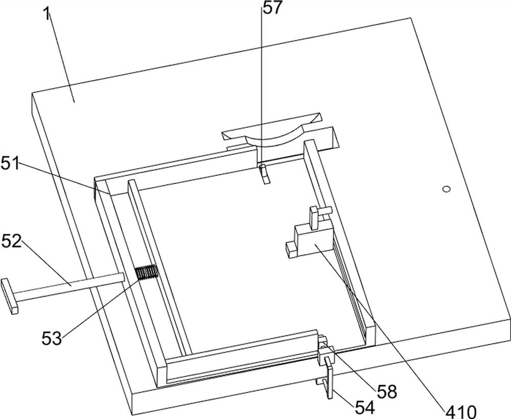
[0036] On the basis of Example 1, such as figure 1 and Figure 9 As shown, fan mechanism 6 is also included, and fan mechanism 6 includes the fifth rotating lever 61, the second belt set 62, the sixth rotating lever 63, the third bevel gear set 64 and fan blade 65, the right side of the middle part on the table 1 The fifth rotating rod 61 of the rotating type, the second belt set 62 is connected with the middle part of the third rotating rod 43 on the lower side of the fifth rotating rod 61, and the sixth rotating rod 63 is connected with the rear side of the right part on the table 1, and the sixth rotating rod The third bevel gear set 64 is connected to the right side of the rod 63 and the upper side of the fifth rotating rod 61 , and the fan blade 65 is connected to the left side of the sixth rotating rod 63 .

[0037] When people are going to process and polish the wooden blocks into wooden strips, they first manually pull the push rod assembly 52, and people put the plan...


PUM


Abstract

The invention relates to grinding equipment, in particular to strip-shaped wood block grinding equipment. The strip-shaped wood block grinding equipment is high in safety and efficiency. The strip-shaped wood block grinding equipment comprises a table, a motor, a first bearing seat, second bearing seats, a grinding mechanism and the like, wherein the motor is installed on the lower side of the rear portion of the table, the first bearing seat is arranged on the rear side of the upper middle portion of the table, the two second bearing seats are arranged on the right side of the table, the grinding mechanism is arranged on the rear side of the upper middle portion of the table and connected with an output shaft of the motor, and a pushing mechanism is arranged in the middle of the upper portion of the t able and connected with the output shaft of the motor. By means of the design of the pushing mechanism, wood boards can be automatically pushed into a grinding tool, people do not need to manually push wood blocks into the grinding tool, and people can grind the wood blocks more safely; and by means of the design of a feeding mechanism, multiple wood blocks can be ground, and people do not need to manually push the wood blocks one by one.

Description

technical field [0001] The invention relates to a grinding device, in particular to a strip-shaped wooden block grinding device. Background technique [0002] Since wood products are widely used now, people have higher and higher requirements for wood processing, and strip-shaped wood blocks are currently the most used one. [0003] At present, when people grind wood blocks, people need to manually put the wood blocks into the grinding tool. After polishing, people need to manually take out the wood strips. During the operation, the wood chips when the wood blocks are polished will hinder the tool from processing the wood blocks. Grinding, the efficiency of grinding wood blocks is low, and the safety is not high. [0004] In response to the above problems, we have designed a strip-shaped wood block grinding device that can automatically feed the wood board into the grinding tool and blow away the wood chips left by the grinding. Contents of the invention [0005] In orde...

Claims


Application Information

Patent Timeline
Patent Type & Authority Applications(China)
IPC IPC(8): B24B19/24B24B27/00B24B41/00B24B55/06
CPCB24B19/24B24B27/0023B24B41/005B24B27/0069B24B55/06
Inventor 陈冬梅
Owner 陈冬梅
Why Eureka
Try Eureka