New energy automobile charging pile

A technology for new energy vehicles and charging piles, applied in electric vehicle charging technology, charging stations, electric vehicles, etc., can solve the problems of damaged charging heads, damaged vehicles and charging piles, and leakage of charging guns, so as to increase the service life. Effect

Active Publication Date: 2021-04-13
镇江领驭立方智能装备有限公司
View PDF10 Cites 4 Cited by
  • Summary
  • Abstract
  • Description
  • Claims
  • Application Information

AI Technical Summary

Problems solved by technology

[0003] However, the existing charging piles for new energy vehicles often cause electric leakage due to long-term friction between the charging cable and the ground because the charging cable is too long, and the charging gun is often exposed, so that it is very likely that the charging head will be damaged by rain in rainy days. Damaged, people often bump into the charging pile when reversing at night because they cannot see, which will cause damage to the vehicle and the charging pile, causing great installation hidden dangers, so we propose a new energy vehicle charging pile to solve the above problems mentioned problem

Method used


Image

  • New energy automobile charging pile
  • New energy automobile charging pile
  • New energy automobile charging pile

Examples


Embodiment 1

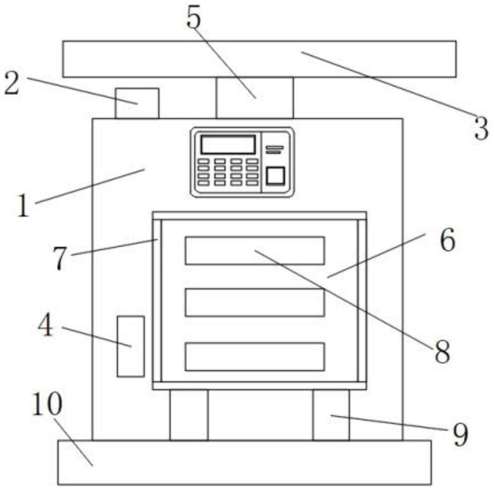
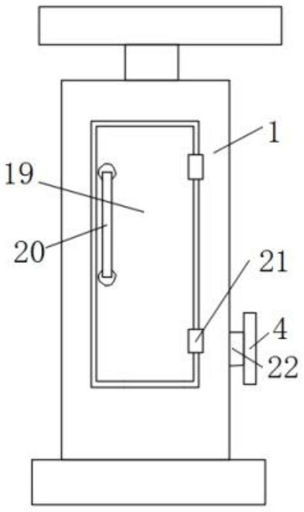
[0031] refer to Figure 1-9, a new energy vehicle charging pile, comprising a charging pile body 1 and a base 10, a sliding box 7 is fixedly connected to one side of the charging pile body 1, a sliding opening is opened at the bottom of the sliding box 7, and the inner wall of one side of the sliding box 7 is fixed The first spring 15 is connected, and the sliding box 7 is slidably connected to the same fixed slide plate 33 close to the inner walls of both sides. One end of the first spring 15 is fixedly connected to the pressure rod 14, and the two ends of the sliding box 7 are provided with a second position sensor. 13, the inner walls of both sides of the sliding box 7 are provided with the same anti-collision assembly, and the bottom of the pressing bar 14 is fixedly connected with two sliding bars 9, and the two ends of the pressing bar 14 are fixedly connected with the bottom of the fixed slide plate 33, and the sliding bar 9 One end of the charging pile extends through ...

Embodiment 2

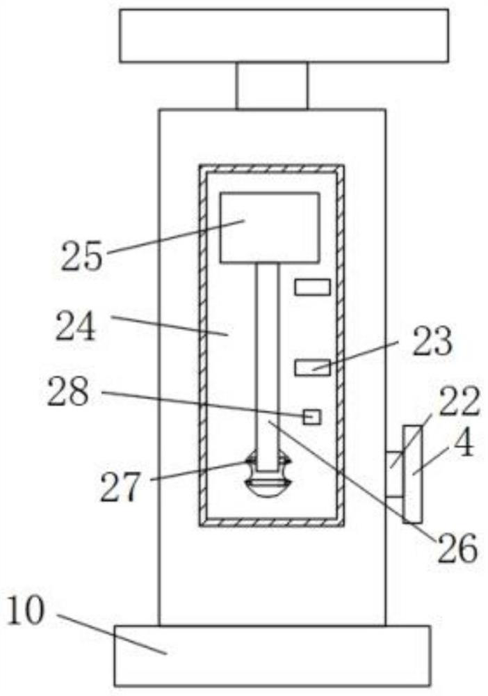
[0033] This embodiment is improved on the basis of Embodiment 1: the anti-collision assembly includes the anti-collision box 6 slidingly connected on both sides of the sliding box 7, the outside of the anti-collision box 6 is provided with a fluorescent lamp 8, and both sides of the anti-collision box 6 are The first position sensor 12 is provided, the second position sensor 13 corresponds to the first position sensor 12, the first position sensor 12 is electrically connected to the alarm 2, and the top inner wall of the crash box 6 is connected to the fixed slide plate 33 The top is fixedly connected with the same shock-absorbing spring 11, and the sliding assembly includes slide rails 17 inlaid on both sides of the base 10. The inner walls of the two slide rails 17 are slidably connected with the same slider 16, and one end of the slide bar 9 is connected to the slide rail. One side of the block 16 is fixedly connected, and the outer side of the slider 16 is fixedly connected...


PUM


Abstract

The invention belongs to the technical field of charging piles, particularly relates to a new energy vehicle charging pile, and aims to solve problems that a vehicle and the charging pile are damaged and great installation hidden dangers are caused due to the fact that people often collide with the charging pile because people cannot see the charging pile when backing up at night. The new energy vehicle charging pile comprises a charging pile body and a base, wherein a sliding box is fixedly connected to one side of the charging pile body, a sliding opening is formed in the bottom of the sliding box, a first spring is fixedly connected to the inner wall of one side of the sliding box, and inner walls of the two sides, close to each other, of the sliding box are slidably connected with the same fixed sliding plate. According to the charging pile, a vehicle owner can be reminded that the charging pile body is collided through the alarm, dual protection can be conducted on the charging pile body through the anti-collision box, the sliding box and the sliding block, and therefore the damage degree of the charging pile body during collision is reduced, and the length of a charging wire can be easily adjusted through the rotating shaft.

Description

technical field [0001] The invention relates to the technical field of charging piles, in particular to a charging pile for new energy vehicles. Background technique [0002] New energy vehicles refer to the use of unconventional vehicle fuels as power sources. The most common is electric vehicles, which need to be charged with charging piles. The function of charging piles is similar to that of fuel dispensers in gas stations. In public buildings (public buildings, shopping malls, public parking lots, etc.) and residential parking lots or charging stations, various types of electric vehicles can be charged according to different voltage levels. The input end of the charging pile is directly connected to the AC grid, and the output end is equipped with a charging plug for charging the electric vehicle. Charging piles generally provide two charging methods: conventional charging and fast charging. People can use a specific charging card to swipe the card on the human-compute...

Claims


Application Information

Patent Timeline
Patent Type & Authority Applications(China)
IPC IPC(8): B60L53/31B60L53/30B60L53/16G08B21/24G08B5/36B65H54/44
CPCB60L53/31B60L53/30B60L53/16G08B21/24G08B5/36B65H54/44Y02T10/70Y02T10/7072Y02T90/12Y02T90/14
Inventor 何锁山
Owner 镇江领驭立方智能装备有限公司
Why Eureka
Try Eureka