High-speed turning belt conveyor line
A belt conveying, high-speed technology, applied in the direction of conveyors, mechanical conveyors, conveyor objects, etc., can solve problems such as detachment, high belt turning speed, and slow feeding, so as to increase the feeding speed and speed of feeding , The effect of civilianization of the device
- Summary
- Abstract
- Description
- Claims
- Application Information
AI Technical Summary
Problems solved by technology
Method used
Image
Examples
Embodiment 1
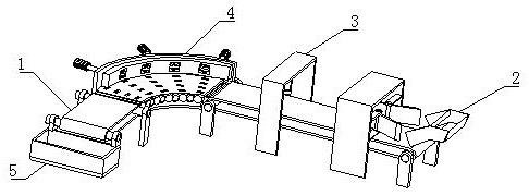
[0031]Such asFigure 1-6As shown, the present invention provides a high-speed turning belt conveying line, including a conveyor belt 1, and the upper surface of the conveyor belt 1 is fixedly mounted, and the upper belt device 2 is attached to the left side and fixed to the conveyor belt 1. The cover device 3 is fixed to the left side and the high-speed turning device 4 is mounted between the conveyor belt 1, and the collecting device 5 is mounted below the left end of the conveyor belt 1.
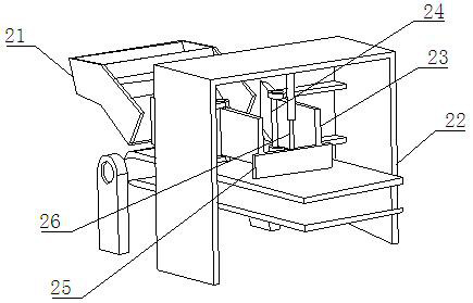
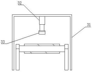
[0032]In the present embodiment, the upper belt device 2 is used for the material of the material, and the capping device 3 is used for the processing of the machine, and the high-speed turning device 4 assists the material to complete the high-speed turning on the conveyor belt, the collecting device 5 is used for the last collect.
[0033]Such asFigure 1-6As shown in the present embodiment, it is preferable that the compression cover device 3 includes a compression glow gantry 31, and the compression...
Embodiment 2
[0035]Such asFigure 1-6As shown, in the basis of the first embodiment, the present invention provides a technical solution: preferably, the high-speed turning device 4 includes a transfer plate 43, and the transfer plate 43 is fixed to the left and right two-shifting belt 1, the transfer plate 43 The surface is fixedly mounted, the transfer device 41 is mounted, the transport panel 43 and the front surface activity are attached, and the turning device 42 includes a turning power device 421 and a transition drum 423, and the transition drum 423 is active and mounted to the transfer plate 43. The surface, the turning power device 421 is active inside the transfer plate 43, and the turning power device 421 is inner array distribution inside the transfer plate 43, and the front end of the turning power device 421 is provided with a reverse cone gear 422, and the turning power device 421 includes The shaft 4212, the shaft 4212 is actively mounted inside the transfer plate 43, and the fro...
Embodiment 3
[0037]Such asFigure 1-6As shown, in the basis of the first embodiment, the present invention provides a technical solution: preferably, the adjustment device 41 includes a fixed adjustment plate 414, and the fixed adjustment plate 414 is fixed to the back surface of the transfer plate 43, and the fixed adjustment plate 414 is fixed. The surface threaded socket has a regulating bolt 411, the front end activity of the adjustment bolt 411 is active, and the active adjustment board 412 is attached to the active adjustment board 413, the buffer accelerator 413 includes a buffer wheel hole 4131, buffer wheel hole 4131 level The array is opened on the front surface of the active adjustment board 412, and the buffer wheel hole 4131 is opened, and the buffer groove 4132 is opened. The buffer groove 4132 is fixed to the left side surface of the buffer groove 4135, and the buffer spring 4135 is fixed to the right end fixed to the buffer shaft 4133, buffer shaft 4133 The center position of the ...
PUM
 Abstract
Description
Claims
Application Information
 - R&D
- Intellectual Property
- Life Sciences
- Materials
- Tech Scout
- Unparalleled Data Quality
- Higher Quality Content
- 60% Fewer Hallucinations
Browse by: Latest US Patents, China's latest patents, Technical Efficacy Thesaurus, Application Domain, Technology Topic, Popular Technical Reports.
© 2025 PatSnap. All rights reserved.Legal|Privacy policy|Modern Slavery Act Transparency Statement|Sitemap|About US| Contact US: help@patsnap.com


