Industrial part equipment transportation robot

A technology of robots and parts, applied in the field of industrial parts and equipment transportation robots, can solve the problems of time-consuming, labor-intensive, easy to lose, etc., and achieve the effect of convenient access, cost saving, and convenient long-distance transportation

Active Publication Date: 2021-04-13
合肥龙智机电科技有限公司
View PDF7 Cites 1 Cited by
  • Summary
  • Abstract
  • Description
  • Claims
  • Application Information

AI Technical Summary

Problems solved by technology

[0002] With the development of society, my country's industrialization process is developing rapidly. In many industrial productions, many parts and components need to be transported from one place to another. Usually, workers put most parts into boxes and transport them at one time. , this period is not only time-consuming and labor-intensive, but also easy to lose

Method used


Image

  • Industrial part equipment transportation robot
  • Industrial part equipment transportation robot
  • Industrial part equipment transportation robot

Examples


Embodiment 1

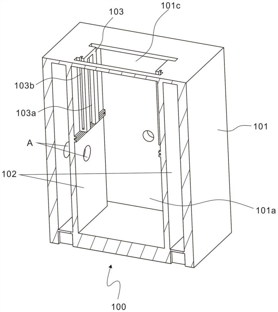
[0028] refer to Figure 1~3 , is the first embodiment of the present invention, which provides an industrial parts equipment transportation robot, which includes a moving module 100 and a storage module 200 for accessing parts and facilitating the storage and delivery of parts in restaurants.

[0029] The mobile module 100 includes a storage box 101, a grid baffle 102 and a slide bar 103. Specifically, a cavity 101a is arranged in the storage box 101, and there are two grid baffles 102, both of which are square plate-shaped structures, vertically and symmetrically arranged in the cavity. Inside the body 101a and the grid baffle 102 is connected from the bottom of the cavity 101a to the top of the cavity 101a, the board surface of the grid baffle 102 is opposite, and there are also two slide bars 103, which are respectively vertically arranged on the grid baffle 102 and opposite to each other. setting, each slide bar 103 has the same structure.

[0030] Further, a T-shaped slo...

Embodiment 2

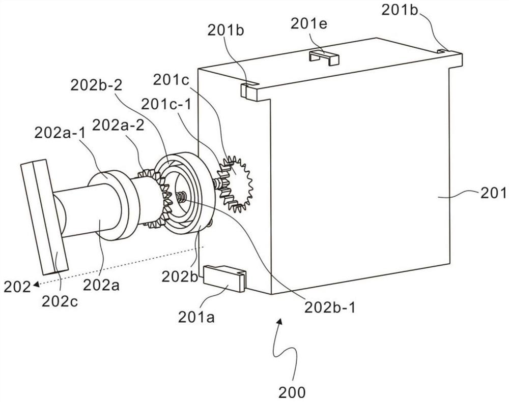
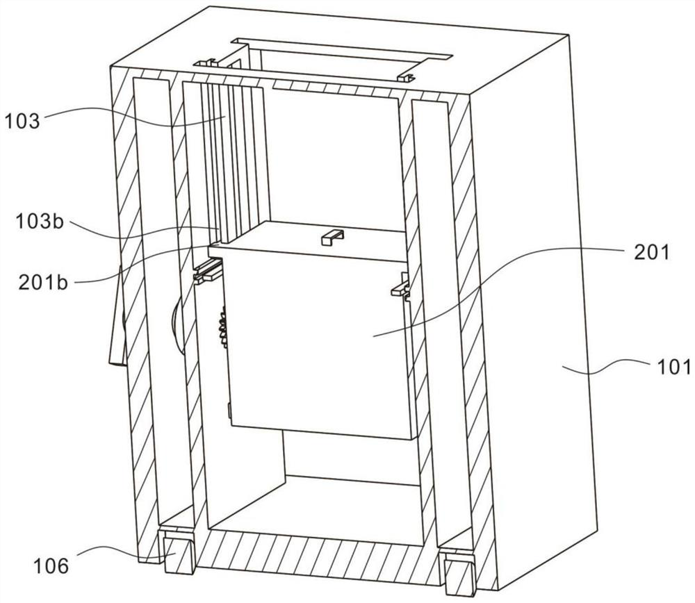
[0037] refer to Figure 4~6 , is the second embodiment of the present invention, which is based on the previous embodiment, and the storage module 200 further includes a limiting plate 204 .

[0038] A concave bar 205 is horizontally arranged below the sliding bar 103 on the grid baffle plate 102, and the two ends of the limiting plate 204 extend into the concave bar 205 to limit the position so that the limiting plate 204 is horizontally erected between the two concave bars 205, Limiting groove 204a is arranged at the bottom of limiting plate 204, and limiting groove 204a is bent at ninety degrees, and block 201d is arranged on part rack 201, and locking block 201d is also curved at ninety degrees, and locking block 201d can cooperate with limiting groove 204a Limiting, when the part rack 201 rotates ninety degrees, the clamping block 201d can rotate and extend into the limiting groove 204a. At this time, the part rack 201 remains in an inclined state under the action of the ...


PUM


Abstract

The invention discloses an industrial part equipment transportation robot. The industrial part equipment transportation robot comprises a moving module and a storage module, the moving module comprises a storage box, grid baffles and sliding strips, a cavity is formed in the storage box, the grid baffles are vertically and symmetrically arranged in the cavity, and the grid baffles are connected to the top of the cavity from the bottom of the cavity; the sliding strips are vertically arranged on the grid baffles and are oppositely arranged; and the storage module comprises a part frame and a rotating part, the part frame is arranged between the grid baffles of the interior of the cavity, the two sides of the part frame are movably connected with the sliding strips, and the rotating part is arranged at one side of the storage box and connected with the part frame. The industrial part equipment transportation robot is used for part conveying in industrial production, parts can be stored in a classified and orderly manner confusion is avoided, manual carrying is not needed, manpower and material resources are saved, and long-distance conveying is facilitated; and meanwhile, cost is saved, operation is easy, and the parts are not prone to being lost.

Description

technical field [0001] The invention relates to the technical field of machinery, in particular to an industrial parts equipment transportation robot. Background technique [0002] With the development of society, my country's industrialization process is developing rapidly. In many industrial productions, many parts and components need to be transported from one place to another. Usually, workers put most parts into boxes and transport them at once. , this period is not only time-consuming and labor-intensive, but also easy to lose. Contents of the invention [0003] The purpose of this section is to outline some aspects of embodiments of the invention and briefly describe some preferred embodiments. Some simplifications or omissions may be made in this section, as well as in the abstract and titles of this application, to avoid obscuring the purpose of this section, the abstract and titles, and such simplifications or omissions should not be used to limit the scope of th...

Claims


Application Information

Patent Timeline
Patent Type & Authority Applications(China)
IPC IPC(8): B65G47/22B65G47/74B65G35/00B65D85/68B65D25/28
CPCB65D25/2826B65D85/68B65G35/00B65G47/22B65G47/74
Inventor 杨浩
Owner 合肥龙智机电科技有限公司
Why Eureka
Try Eureka