Novel electric parking door hinge

A parking and hinge technology, applied in the field of door hinges, can solve the problems of affecting the appearance, slightly opening, sometimes requiring half-opening, sometimes requiring full opening, destroying the integrity, etc., to achieve the effect of novel and practical design

Active Publication Date: 2021-04-13
ZHEJIANG DINGLI IND
View PDF10 Cites 2 Cited by
  • Summary
  • Abstract
  • Description
  • Claims
  • Application Information

AI Technical Summary

Problems solved by technology

[0002] In our life, doors are everywhere, but in the process of using the door, sometimes it needs to be slightly opened, sometimes it needs to be half opened, and sometimes it needs to be fully opened. In short, people need the door to stop at different angles. As for how to position the door, after the door is opened, if it cannot be positioned properly, the door will be forced to close due to wind or collision, and sometimes the door will be damaged. The current solution on the market is to choose a door stopper, but On the one hand, the door stopper is only used for the fully open state of the door. On the other hand, during the installation process of the door stopper, it is necessary to punch holes on the door, or on the floor, or on the wall. , this will destroy the integrity and affect the appearance, and if the wall and the ground are all ceramic tiles, it will be difficult to punch holes on it, which will destroy the integrity of the wall or the ground. However, there are still some defects such as use effect and automation, and a new type of electric parking door hinge can solve the problem

Method used


Image

  • Novel electric parking door hinge
  • Novel electric parking door hinge
  • Novel electric parking door hinge

Examples


Embodiment Construction

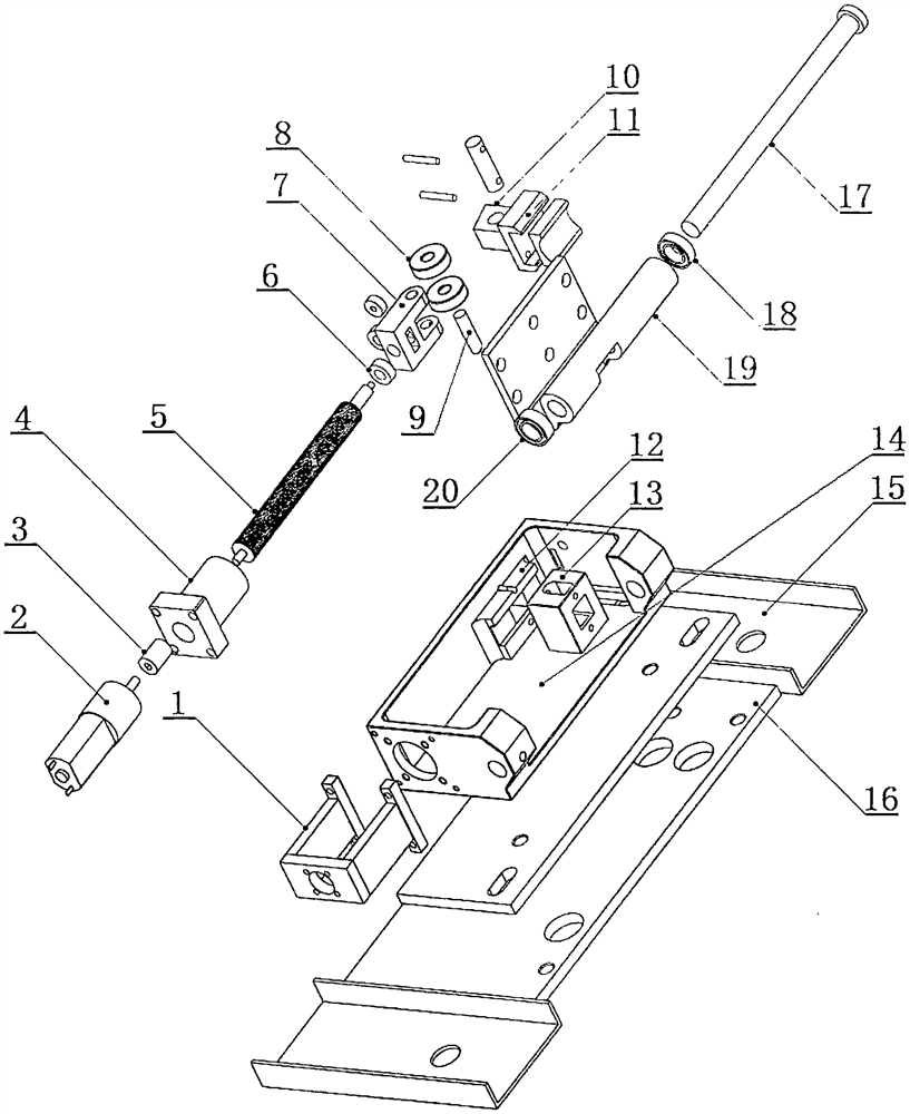
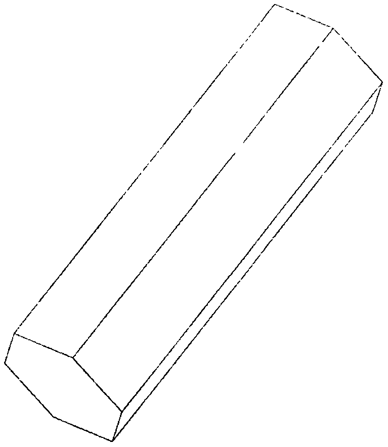
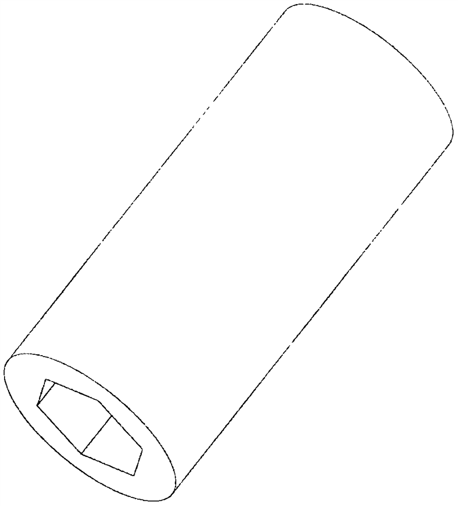
[0020] Such as figure 1 is a schematic diagram of the explosion of the present invention, such as figure 2 is an enlarged schematic diagram of the hexagonal rod of the coupling, such as image 3 It is an enlarged schematic diagram of the inner hexagonal cylinder of the coupling, such as Figure 4 It is an enlarged schematic diagram of the main body of the hinge, such as Figure 5 It is a schematic diagram of the present invention, which is installed on the door frame for parking at any angle position of the door, driven by a 9-volt micro DC motor, including a power transmission part, a roller mechanism, a parking mechanism and a hinge part, and the power transmission part includes a motor frame 1 , motor 2, shaft coupling 3, ball screw nut 4, ball screw screw 5, several gaskets I6 and a wired switch located on the door handle, ball screw nut 4 cooperates with ball screw screw 5, and motor 2 is installed For the motor frame 1, the model of the motor 2 is IG220104-201M1R, DC...


PUM


Abstract

The invention relates to a door hinge, in particular to a novel electric parking door hinge. The novel electric parking door hinge comprises a power transmission part, a idler wheel mechanism, a parking mechanism and a hinge part; the power transmission part is provided with a motor frame, a motor, a coupler, a ball screw nut and a ball screw rod; the coupler comprises a hexagonal rod and an inner hexagonal cylinder which are in sliding fit with each other, one end of the hexagonal rod is connected with a motor shaft, the other end of the hexagonal rod is inserted into one end of the inner hexagonal cylinder to form sliding connection, and the other end of the inner hexagonal cylinder is connected with the tail end of the ball screw rod; the idler wheel mechanism is provided with an idler wheel connector and an idler wheel, and the other end of the idler wheel connector is connected with the top end of the ball screw rod through a gasket I; the parking mechanism is provided with a trapezoidal sliding block, a brake pad assembly, an idler wheel groove and a sliding block groove which are connected with one another, wherein the trapezoidal sliding block is provided with a springback device; and the hinge part is provided with a hinge main body and a hinge mandrel, and a hinge blade is provided with a mandrel sleeve. When the idler wheel abuts against the inclined face of the trapezoidal sliding block with the springback device from the position between the idler wheel groove and the sliding block groove, a brake pad is driven to tightly hold the mandrel sleeve of the hinge blade, and door parking is achieved.

Description

technical field [0001] The invention relates to a door hinge, in particular to a novel electric parking door hinge which is driven by a tiny DC motor and can be parked at any time and self-locked. Background technique [0002] In our life, doors are everywhere, but in the process of using the door, sometimes it needs to be slightly opened, sometimes it needs to be half-opened, and sometimes it needs to be fully opened. As for how to position the door, after the door is opened, if it cannot be positioned properly, the door will be forced to close due to wind or collision, and sometimes the door will be damaged. The current solution on the market is to choose a door stopper, but On the one hand, the door stopper is only used for the fully open state of the door. On the other hand, during the installation process of the door stopper, it is necessary to punch holes on the door, or on the floor, or on the wall. , this will destroy the integrity and affect the appearance. Moreove...

Claims


Application Information

Patent Timeline
Patent Type & Authority Applications(China)
IPC IPC(8): E05D3/02E05D5/02E05D5/12E05D11/10E05F15/622
CPCE05D3/02E05D5/02E05D5/12E05D11/1028E05F15/622E05Y2900/132
Inventor 俞云祥刘勇灿谢妃潘伟华邢伟勇
Owner ZHEJIANG DINGLI IND
Why Eureka
Try Eureka