Turbine last-stage long blade torsional vibration stress obtaining method based on finite elements

A technology of vibration stress and acquisition method, which is applied in the direction of machines/engines, mechanical equipment, engine components, etc., can solve problems such as the inability to predict the safety of the last stage blades of steam turbines, and achieve the effect of avoiding accidents

Inactive Publication Date: 2021-04-13
HARBIN TURBINE
View PDF5 Cites 6 Cited by
  • Summary
  • Abstract
  • Description
  • Claims
  • Application Information

AI Technical Summary

Problems solved by technology

[0004] The purpose of the present invention is: to solve the problem that the dynamic stress value obtained in the prior art cannot predict the safety of the last-stage blade of the steam turbine when the shaft system is subjected to torsional vibration, and propose a finite element-based torsional vibration analysis method for the last-stage long blade of the steam turbine. stress acquisition method

Method used


Image

  • Turbine last-stage long blade torsional vibration stress obtaining method based on finite elements
  • Turbine last-stage long blade torsional vibration stress obtaining method based on finite elements
  • Turbine last-stage long blade torsional vibration stress obtaining method based on finite elements

Examples


specific Embodiment approach 1

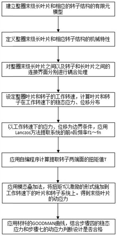
[0031] Specific implementation mode one: refer to figure 1 This embodiment is specifically described. A finite element-based method for obtaining torsional vibration stress of the last-stage long blade of a steam turbine described in this embodiment includes:

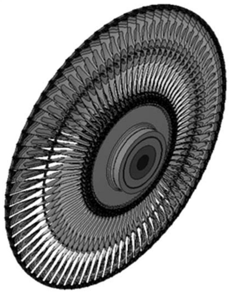
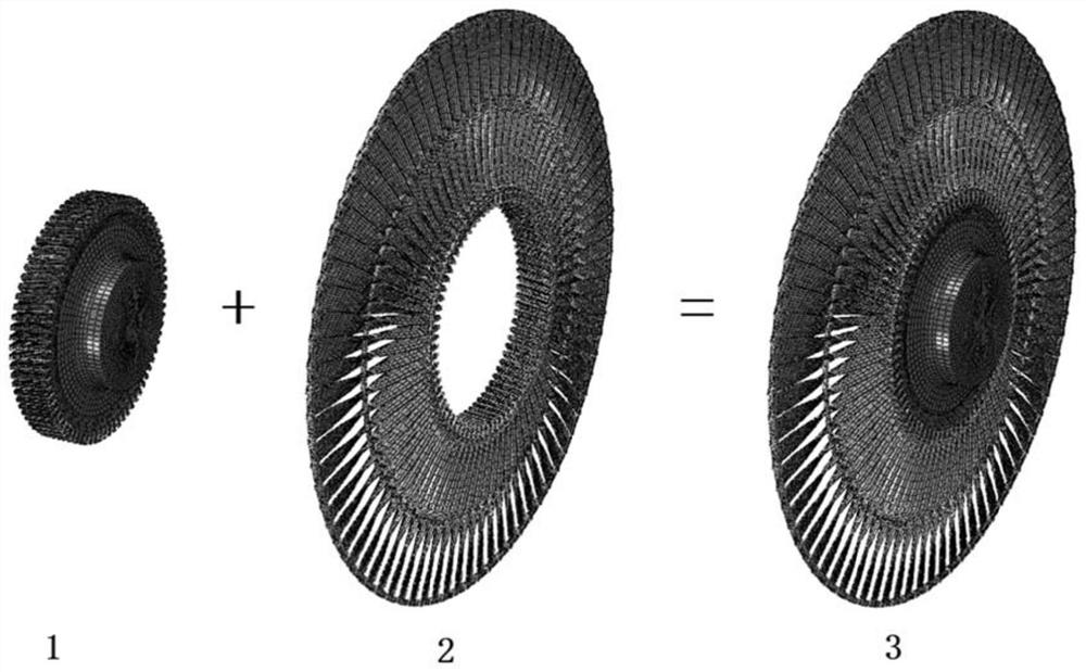
[0032] Step 1: Establish the finite element model of the last-stage long blade and the corresponding rotor structure of the whole circle;

[0033] Step 2: Define the mechanical characteristics of the last stage long blade and the corresponding rotor structure in the finite element model;

[0034] Step 3: Perform coupling processing on the defined connection interfaces between the last-stage long blades of the entire circle and between the corresponding rotor and the last-stage long blades of the entire circle;

[0035] Step 4: Set the operating speed for the full circle of last-stage long blades and corresponding rotors after coupling processing, and then calculate the steady-state stress and displacement distribution ...

specific Embodiment approach 2

[0039] Embodiment 2: This embodiment is a further description of Embodiment 1. The difference between this embodiment and Embodiment 1 is that the mechanical characteristics include damping characteristics and elastic modulus.

specific Embodiment approach 3

[0040] Embodiment 3: This embodiment is a further description of Embodiment 1. The difference between this embodiment and Embodiment 1 is that the Lanczos method is used to extract the first n-order frequency f in the step 5. 1 ~ f n .


PUM


Abstract

The invention discloses a turbine last-stage long blade torsional vibration stress obtaining method based on finite elements, relates to the field of turbine design, and aims to solve the problem that a dynamic stress value obtained in the prior art cannot predict the safety of a turbine last-stage blade when a shafting is subjected to torsional vibration. Due to the fact that the torque value T of the shafting is closely related to long blade dynamic stress distribution caused by torsional vibration when a power grid is in transient imbalance, finite element solving is conducted on the stress of the whole circle of blades and the corresponding rotor structure at the working rotating speed; a stress-strain distribution value of each node is obtained, and first n-order frequencies f1-fn of the system are extracted by utilizing a Lanczos method; and the torque value T of the shafting is applied to the system as excitation when the transient state of the power grid is unbalanced, a modal superposition method is applied, and the dynamic stress value of the last-stage long blade is obtained. The dynamic stress value obtained through the calculation method can predict the safety of the turbine last-stage blade when the shafting is subjected to torsional vibration, and therefore accidents are avoided.

Description

technical field [0001] The invention relates to the field of steam turbine design, in particular to a finite element-based method for obtaining torsional vibration stress of long blades in the last stage of a steam turbine. Background technique [0002] The shaft system of the steam turbine generator set is composed of multiple rotors, and the moving blades are installed on the rotors in a complete circle according to certain rules. With the increase of steam turbine power and steam initial parameters, the number of rotors in the shaft system increases, the shaft system becomes relatively slender, and the final stage blades of the steam turbine become longer and longer. At present, the long blades of the last stage of thermal power full-speed units have reached more than 1.2 meters, and the long blades of the last stage of nuclear power half-speed units have reached more than 1.8 meters. When the power grid is unbalanced, under the action of alternating torque, the shafting...

Claims


Application Information

Patent Timeline
Patent Type & Authority Applications(China)
IPC IPC(8): F01D21/00F01D21/14F01D25/00G06F30/20
CPCF01D21/003F01D21/14F01D25/00G06F30/20
Inventor 马义良郭魁俊李绪瑞关淳翁振宇李宇峰潘劭平初世明田宇张迪张远刘洋武芏茳李央
Owner HARBIN TURBINE
Why Eureka
Try Eureka