Eureka AIR delivers breakthrough ideas for toughest innovation challenges, trusted by R&D personnel around the world.

Installation method of accident oil discharge device of high-end converter transformer

A converter transformer and installation method technology, applied in the direction of transformer/inductor cooling, switchgear, electrical components, etc., can solve the problems of fire spread, damage to the converter valve, fire and explosion, etc., and achieve scientific and economical installation methods. Labor cost, the effect of ensuring consistency

Pending Publication Date: 2021-04-13
TBEA SHENYANG TRANSFORMER GRP CO LTD +1
View PDF0 Cites 0 Cited by
  • Summary
  • Abstract
  • Description
  • Claims
  • Application Information

AI Technical Summary

Problems solved by technology

The converter transformer is an oil-immersed transformer. Once a failure occurs, it is easy to cause fire and explosion. The existence of a large amount of transformer oil in the box may cause the fire to spread uncontrollably, and even damage the converter valve.
The oil drain valve set on the main body of the converter transformer oil tank needs to be manually operated, and personnel cannot approach it in the event of a fire
At present, the converter transformers running online are generally not equipped with remote automatic oil discharge devices, so once a fire occurs, the loss will be very large. What is more important is how to install the oil discharge device on the converter transformer body of the existing converter station and carry out corresponding measures. Process treatment

Method used


Image

  • Installation method of accident oil discharge device of high-end converter transformer
  • Installation method of accident oil discharge device of high-end converter transformer
  • Installation method of accident oil discharge device of high-end converter transformer

Examples


Embodiment Construction

[0032] In order to make the object, technical solution and advantages of the present invention clearer, the present invention will be described in detail below in conjunction with the accompanying drawings and specific embodiments.

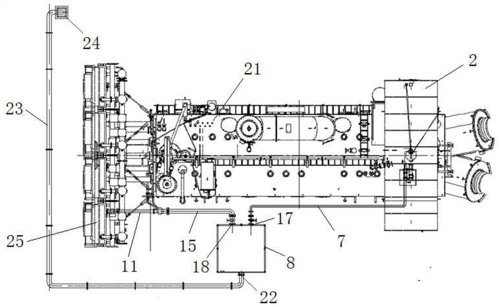
[0033] A method for installing an emergency oil discharge device for a high-end converter transformer, comprising the following steps:

[0034] Step 1): Cut off the power of the converter transformer, and put it in the state of shutting down for maintenance, and add an oil storage pool to store the transformer oil discharged after the accident.

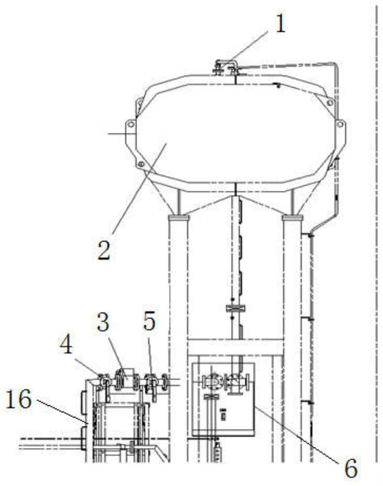
[0035] Step 2): Drain the transformer oil in the oil conservator 2 .

[0036] First of all, in the maintenance state, the valve a4 and the valve b5 at both ends of the gas relay 3 on the main gas connection pipe 16 of the converter transformer are closed first, and the gas relay 3 is removed.

[0037] Since the installed oil discharge device needs to be processed accordingly, the transformer oil in the o...


PUM


Abstract

The invention relates to the technical field of converter transformer safety, and especially relates to an installation method of a high-end converter transformer accident oil discharge device. The installation method comprises the following steps: (1) powering off the converter transformer, staying is in a shutdown maintenance state, and additionally arranging an oil storage pool for storing transformer oil discharged after an accident happens; 2) discharging the transformer oil in the oil conservator; 3) installing an oil discharge pipeline and a cutoff module of the oil conservator; 4) installing a remote control automatic oil discharge module; 5) installing a main body oil discharge pipeline and a cooler oil discharge pipeline; 6) mounting an oil unloading pipeline; 7) vacuumizing the oil conservator oil discharge pipeline, the main body oil discharge pipeline and the cooler oil discharge pipeline; and 8) performing oil injection treatment on the oil conservator oil discharge pipeline, the main body oil discharge pipeline and the cooler oil discharge pipeline, and supplementing oil to the oil conservator. According to the invention, the process of additionally arranging the oil discharge device under the condition that the converter transformer does not quit power grid operation is realized, and extra huge economic loss is not caused.

Description

technical field [0001] The invention relates to the technical field of converter transformer safety, in particular to an installation method of a high-end converter transformer accident oil discharge device. Background technique [0002] At present, the converter transformer is one of the important equipment in the HVDC power transmission system. It is usually connected with the converter valve to form a converter unit to realize the mutual conversion of AC and DC, and realize the mutual electrical isolation of AC and DC. The converter transformer is an oil-immersed transformer. Once a fault occurs, it is easy to cause fire and explosion. The existence of a large amount of transformer oil in the box may cause the fire to spread uncontrollably, and even damage the converter valve. The oil drain valve provided on the main body of the converter transformer oil tank needs to be manually operated, and personnel cannot approach it in case of a fire. At present, the converter tran...

Claims


Application Information

Patent Timeline
IPC IPC(8): H01F27/14H02B3/00
CPCH01F27/14H02B3/00
Inventor 宋军翰李成顺李赫刘媛媛
Owner TBEA SHENYANG TRANSFORMER GRP CO LTD
Why Eureka
Eureka Blog
Learn More