Vertical routing equipment and routing method

A technology of equipment and metal wires, which is applied in the field of vertical wire bonding equipment and wire bonding, can solve the problems of limited length of vertical metal wires and prone to offset, so as to reduce process cost and process time, avoid offset, and improve transmission efficiency effect

Pending Publication Date: 2021-04-13
SJ SEMICON JIANGYIN CORP
View PDF0 Cites 0 Cited by
  • Summary
  • Abstract
  • Description
  • Claims
  • Application Information

AI Technical Summary

Problems solved by technology

[0004] In view of the above-mentioned shortcomings of the prior art, the object of the present invention is to provide a vertical wire bonding device and a wire bonding method, which are used to solve the problems of limited length of vertical metal wires and easy deviation in the prior art

Method used


Image

  • Vertical routing equipment and routing method
  • Vertical routing equipment and routing method
  • Vertical routing equipment and routing method

Examples


Embodiment Construction

[0033] Embodiments of the present invention are described below through specific examples, and those skilled in the art can easily understand other advantages and effects of the present invention from the content disclosed in this specification. The present invention can also be implemented or applied through other different specific implementation modes, and various modifications or changes can be made to the details in this specification based on different viewpoints and applications without departing from the spirit of the present invention.

[0034] For example, when describing the embodiments of the present invention in detail, for the convenience of explanation, the cross-sectional view showing the device structure will not be partially enlarged according to the general scale, and the schematic diagram is only an example, which should not limit the protection scope of the present invention. In addition, the three-dimensional space dimensions of length, width and depth sho...


PUM

PropertyMeasurementUnit
heightaaaaaaaaaa

Abstract

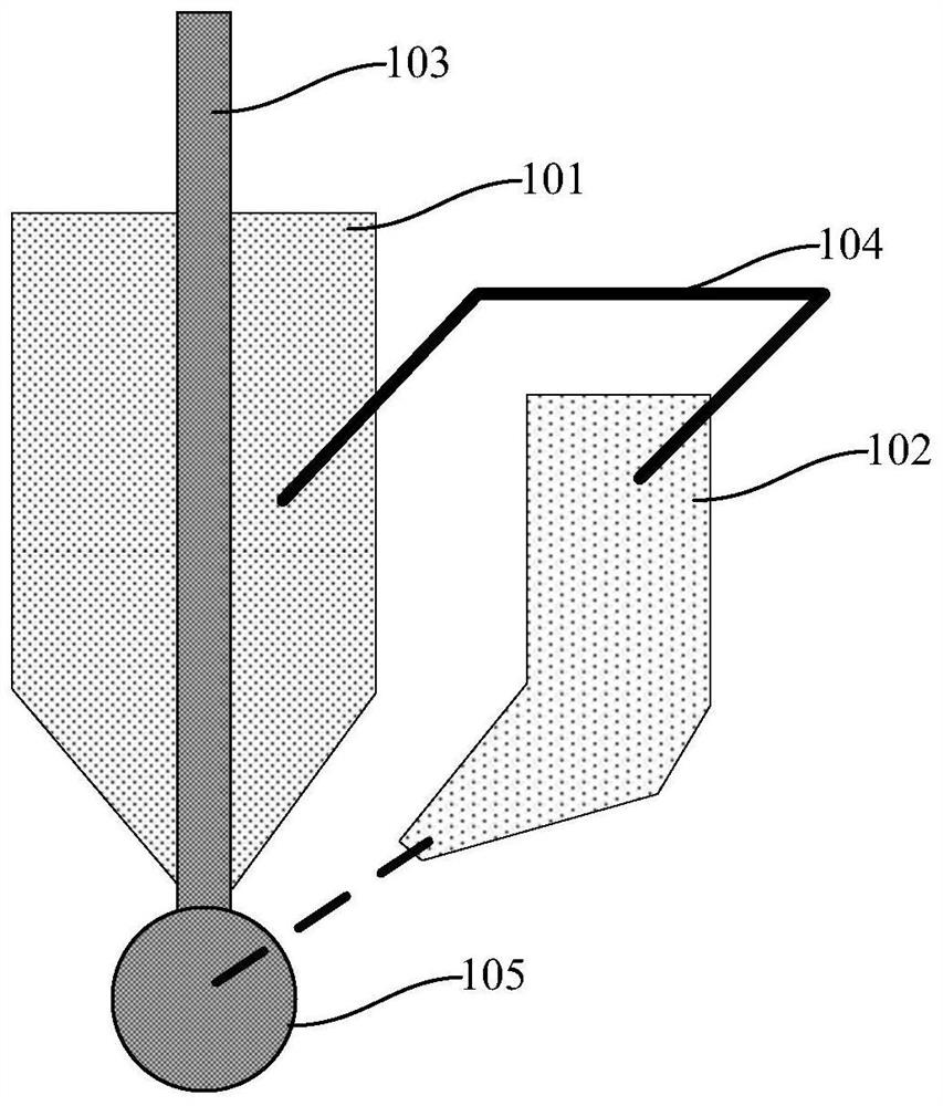
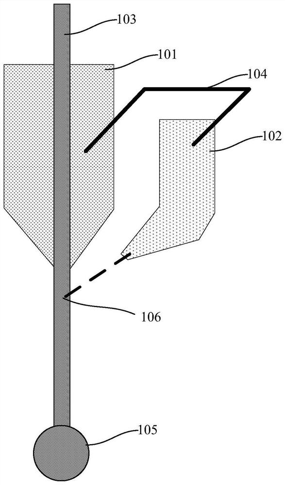
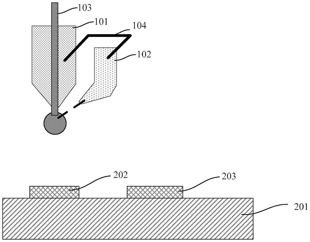
The invention provides vertical routing equipment and a routing method. The equipment comprises: a chopper which is provided with a wire hole for a metal wire to pass through; a cutter aligned to a target cutting point on the outer side of the lower port of the chopper and used for cutting the metal wire from the target cutting point and melting the end of the metal wire to form a metal ball; and a moving device providing vertical movement of the chopper and the cutter, and enabling the cutter to be always aligned with a target cutting point on the outer side of the lower port of the chopper. The cutter and the chopper are fixed together to move up and down at the same time, and the vertical routing height is not affected due to the fact that the cutter and the chopper are fixed, so the length limitation of the vertical metal wire can be eliminated, and the vertical metal wire with the large length can be obtained; and meanwhile, the vertical metal wire cannot be bent additionally, so the metal wire can be prevented from deviating relative to the center of the bottom ball.

Description

technical field [0001] The invention relates to the field of semiconductor packaging, in particular to a vertical wire bonding device and a wire bonding method. Background technique [0002] In recent years, "faster, smaller, cheaper, and more reliable" has become the goal driving the development of the semiconductor technology field. In the field of semiconductor manufacturing, the density of integrated circuits is increased by continuously reducing the minimum feature size and increasing packaging stacks to meet the goal of "smaller". On this basis, "faster, cheaper, and more reliable" cannot be ignored. [0003] All computing and communication systems of integrated circuits need to be powered by the power transmission subsystem. The power transmission subsystem converts the high voltage of the power supply into different voltages required by each discrete device in the integrated circuit and transmits them. In stacked package chips, the connection Each layer of chips and...

Claims


Application Information

Patent Timeline
Patent Type & Authority Applications(China)
IPC IPC(8): H01L21/67B23K26/38B23K7/00B23K101/40
CPCB23K7/00B23K26/38B23K2101/40H01L21/67138H01L24/745H01L2224/745
Inventor 黄晗林正忠吴政达陈彦亨赵梦波
Owner SJ SEMICON JIANGYIN CORP
Why Eureka
Try Eureka