
Distributed photovoltaic power station system and reactive self-balancing control method

A distributed photovoltaic and photovoltaic power generation system technology, applied in photovoltaic power generation, reactive power compensation, reactive power adjustment/elimination/compensation, etc. Issues such as the sequence of reactive power adjustment of photovoltaic inverters, to achieve the effect of avoiding misoperation, avoiding reactive power burden, and eliminating influence

Active Publication Date: 2021-04-13
ZHUZHOU NAT ENG RES CENT OF CONVERTERS
View PDF10 Cites 1 Cited by
  • Summary
  • Abstract
  • Description
  • Claims
  • Application Information

AI Technical Summary

Problems solved by technology

[0006] However, in the actual application of the above-mentioned traditional inverter power factor adjustment scheme, it is impossible to guarantee the sequence of the reactive power adjustment of the photovoltaic inverter and the switching of the low-voltage capacitor. In the process, the inverter first outputs reactive power. When the reactive power output of the inverter reaches the upper limit, the low-voltage compensation capacitor is put into operation; Before the upper limit is reached, the capacitor has no chance to be put into operation again, that is, the reactive power regulation of the inverter will have the same effect as the capacitor regulation, and the fine-tuning of the inverter on the basis of capacitance compensation cannot be realized. The above regulation scheme is usually used in practical applications. is invalid and cannot achieve the desired adjustment effect

Method used


Image

  • Distributed photovoltaic power station system and reactive self-balancing control method
  • Distributed photovoltaic power station system and reactive self-balancing control method
  • Distributed photovoltaic power station system and reactive self-balancing control method

Examples


Embodiment Construction

[0036]The present invention will be further described below in conjunction with the accompanying drawings and specific preferred embodiments, but the protection scope of the present invention is not limited thereby.

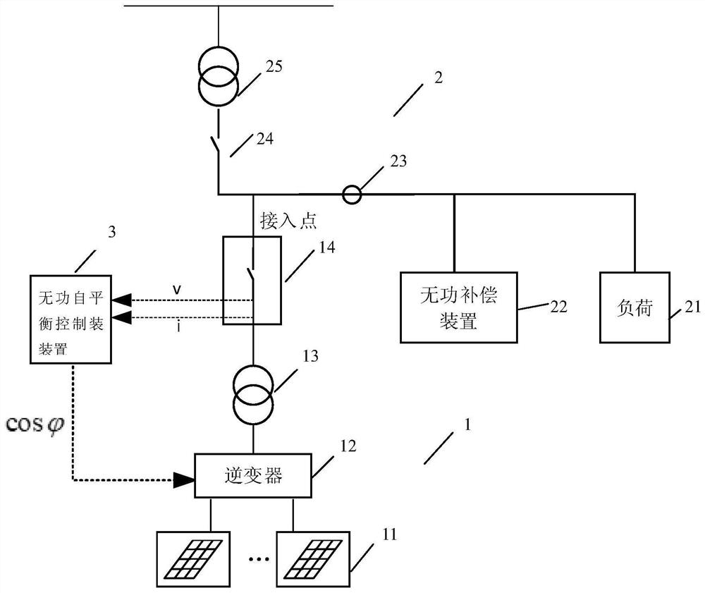
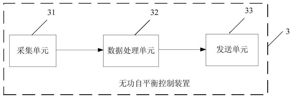
[0037] Such as figure 1 As shown, the distributed photovoltaic power station system with reactive power self-balancing function in this embodiment includes a photovoltaic power generation system 1, and the photovoltaic power generation system 1 includes photovoltaic modules 11, grid-connected inverters 12, photovoltaic transformers 13 and access modules connected in sequence 14. The output end of the access module 14 is connected to the user's low-voltage power distribution system 2, and also includes a reactive power self-balancing control device 3 connected to the photovoltaic power generation system 1, and the input end of the reactive power self-balancing control device 3 is connected to the access module 14. The control output terminal is connected to the gr...


PUM


Abstract

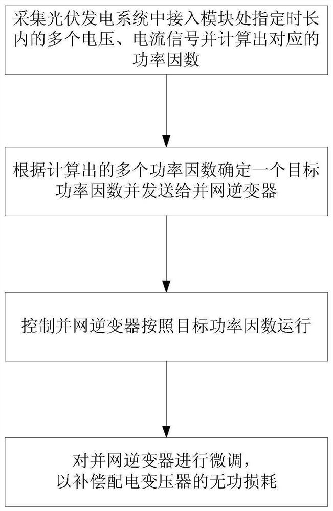
The invention discloses a distributed photovoltaic power station system and a reactive self-balancing control method. The system comprises a photovoltaic power generation system, the photovoltaic power generation system comprises a photovoltaic module, a grid-connected inverter, a photovoltaic transformer and an access module which are connected in sequence, and the output end of the access module is connected to a user low-voltage power distribution system. The system further comprises a reactive self-balancing control device connected with the photovoltaic power generation system, and the reactive self-balancing control device collects a plurality of voltage and current signals at the access module within a specified time length, calculates a corresponding power factor, determines a target power factor according to each calculated power factor and sends the target power factor to the grid-connected inverter to control the grid-connected inverter to operate according to the target power factor. The system has the advantages of being simple in structure, low in cost, capable of achieving reactive self-balance and improving the power factor of a gateway point, good in reactive adjustment control effect and the like.

Description

technical field [0001] The invention relates to the technical field of distributed photovoltaic power stations, in particular to a distributed photovoltaic power station system and a reactive power self-balancing control method. Background technique [0002] Distributed photovoltaic power stations are mostly built in industrial factories or business parks, and use medium and low voltage to connect to the user grid. The power generated is mainly for self-use and consumption nearby, and the remaining power is connected to the grid. During the operation of distributed photovoltaic power plants, there are often prominent power factor problems. For example, the power factor of the distribution gateway in the factory area is unqualified, which increases the power factor to adjust the electricity bill. Some photovoltaic power plants are even forced to shut down. Both users and power generation companies have caused economic losses that cannot be ignored. The main reasons for the u...

Claims


Application Information

Patent Timeline
Patent Type & Authority Applications(China)
IPC IPC(8): H02J3/38H02J3/50H02J3/18
CPCH02J3/50H02J3/18Y02E10/56Y02E40/30
Inventor 吴恒亮陈嘉贵翟文杰李建程宇旭武宇龙刘特安孙艳明高峰李庆武刘程
Owner ZHUZHOU NAT ENG RES CENT OF CONVERTERS
Learn More