
Automatic deep cavity cleaning device

An automatic cleaning and deep cavity technology, which is used in devices that apply liquid to the surface, cleaning hollow objects, cleaning methods and utensils, etc. problems, to achieve the effect of facilitating rapid replacement, strengthening cleaning and protection effects, and smoothing the cleaning process without lag

Active Publication Date: 2021-04-16
南京天祥智能设备科技有限公司
View PDF13 Cites 3 Cited by
  • Summary
  • Abstract
  • Description
  • Claims
  • Application Information

AI Technical Summary

Problems solved by technology

[0006] In view of this, the present invention aims to propose a deep cavity automatic cleaning device, which can solve the technical problems in the prior art that the internal cleaning cannot be completed due to the long pipeline or the cleaning device is stuck, and the cleaning effect is not good

Method used


Image

  • Automatic deep cavity cleaning device
  • Automatic deep cavity cleaning device
  • Automatic deep cavity cleaning device

Examples


Embodiment 1

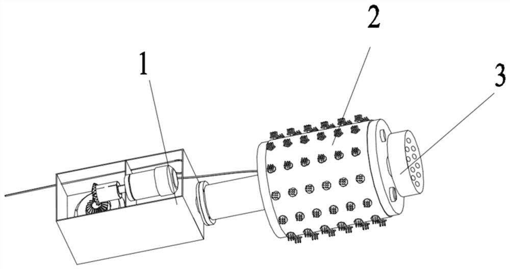
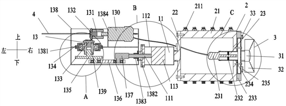
[0036] Embodiment one, such as Figure 1 to Figure 6 As shown, a deep cavity automatic cleaning device includes an actuator, and the actuator includes a power module 1, a cleaning module 2 and a detection module 3; one end of the cleaning module 2 is detachably and fixedly connected to the power module 1, and the other end is connected to the power module 1. The detection module 3 is detachably fixedly connected.

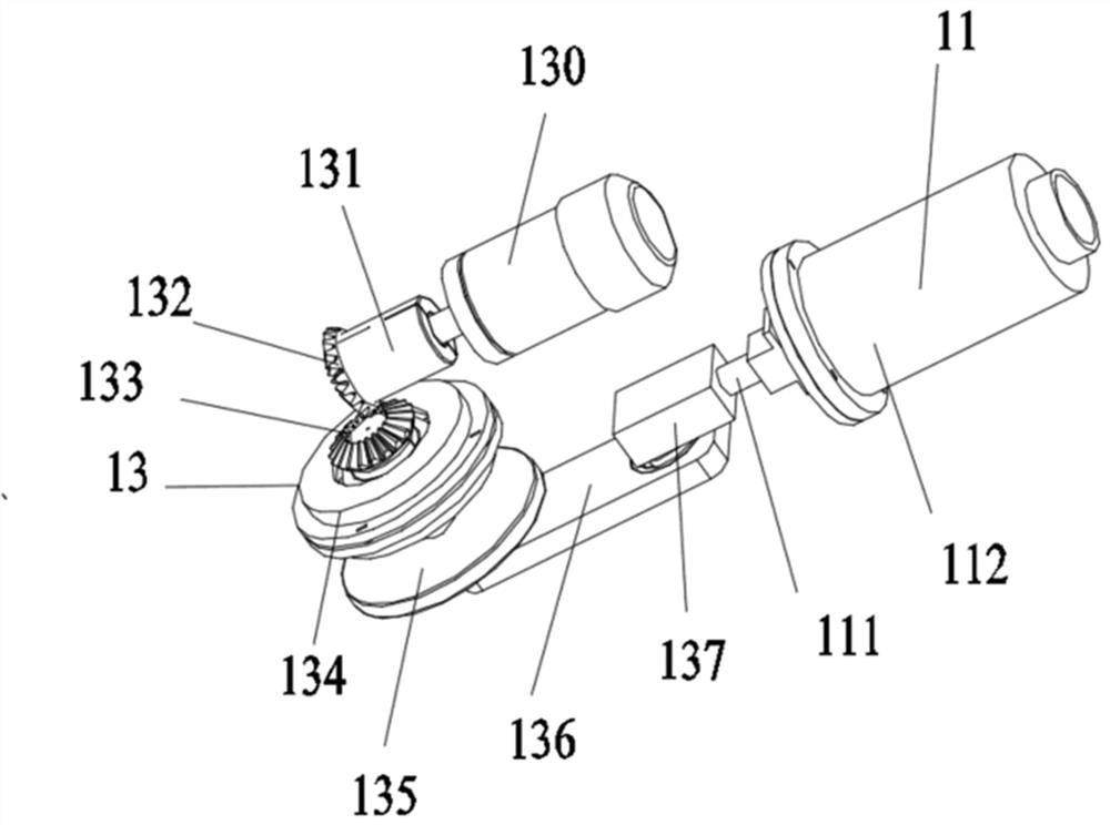
[0037] Further, the power module 1 includes a first power part 13 and a piston cylinder 11, the piston cylinder 11 includes a cylinder body 112, a piston rod 111 and a piston 113, and the cylinder body 112 is fixedly connected to the first power part 13 , the piston 113 is arranged in the cylinder body 112 and can reciprocate, one end of the piston rod 111 extends into the cylinder body 112 and is fixedly connected with the piston 113, and the other end extends out of the cylinder body 112 to drive the piston 113 to reciprocate Movement; one end of the cylinder bod...

Embodiment 2

[0048] Embodiment two, such as Figure 7 and Figure 8 As shown, the power part of the power module 1 of this embodiment is different from that of the first embodiment, and is used to solve the situation that the center of gravity of the power part shifts in the first embodiment, which causes the actuator to shake slightly when moving forward. The power module 1 includes a second power part 12 and Piston cylinder 11, the second power part 12 comprises support 121, second motor 122, connecting plate 123, slide block 124, guide rail 125 and fixed plate 126, and support 121 is L-shaped, and bottom plate end is fixedly connected with fixed plate 126, Forming a U shape, the outer side of the fixing plate 126 is fixedly connected to the first connecting end 1121, and the piston rod 111 passes through the fixing plate 126 and is connected to the second motor 122. The second motor 122 is a voice coil motor and includes a fixed end and an output end. The fixed end is a magnet, and the...


PUM


Abstract

The invention provides an automatic deep cavity cleaning device, which comprises an actuator, and the actuator comprises a power module, a cleaning module and a detection module; one end of the cleaning module is detachably and fixedly connected with the power module, and the other end of the cleaning module is detachably and fixedly connected with the detection module; the power module comprises a power part and a piston cylinder, and the power part drives a piston to reciprocate in the piston cylinder to generate axial reciprocating impact force to provide power for the actuator to move in a pipeline deep cavity; the cleaning module comprises a brush and an oiler; the end of the brush is connected with the oiler, and cleaning and protection of the deep cavity can be achieved; the detection module can conduct image collection and distance detection, and feed back the cleaning condition in the cavity in real time; and the bending moment generated by the brush and the impact force generated by the piston work together to enable the actuator to travel and clean in a pipeline. The automatic deep cavity cleaning device provided by the invention can adapt to pipelines of different types, can achieve automatic deep cavity cleaning, is not limited by using conditions, and is smooth in cleaning process and good in cleaning effect.

Description

technical field [0001] The invention relates to the technical field of pipeline cleaning devices, in particular to a deep cavity automatic cleaning device. Background technique [0002] Pipes are widely used, mainly used in water supply, drainage, heat supply, gas supply, long-distance transportation of oil and natural gas, agricultural irrigation, hydraulic engineering, weapons and various industrial devices. Large, long-term use inside the pipeline will cause impurities such as sediment on the inner wall. If the sediment adheres to the inner wall of the pipeline for a long time, it will lead to accelerated corrosion inside the pipeline. Therefore, the pipeline must be cleaned and rust-proofed regularly during use. [0003] When the common pipeline is long, the inner wall cleaning device is inconvenient to be inserted into the pipeline, and the inner wall of the pipeline cannot be cleaned. It is difficult to completely clean up the reactants remaining on the inner wall of t...

Claims


Application Information

Patent Timeline
Patent Type & Authority Applications(China)
IPC IPC(8): B08B9/049B08B13/00B05C7/08
Inventor 刘漫贤许文哲滕承武袁晓敏
Owner 南京天祥智能设备科技有限公司
Learn More