
Laser marking machine

A marking machine and laser technology, applied in the direction of laser welding equipment, auxiliary equipment, auxiliary welding equipment, etc., can solve the problems of abnormal movement, unstable placement, and offset in the processing process, so as to ensure the stability of placement, the stability of the lower part, The effect of increasing friction

Pending Publication Date: 2021-04-16
黄涛
View PDF3 Cites 0 Cited by
  • Summary
  • Abstract
  • Description
  • Claims
  • Application Information

AI Technical Summary

Problems solved by technology

[0002] With the development of science and technology and the improvement of residents' living standards, various manual DIY entertainment activities are gradually emerging. As for laser marking technology, there are laser marking machines with various formats on the market. However, for some civilian laser marking machines Generally speaking, because the placement environment is too random, the placement of the workpiece to be processed and the abnormal movement during the processing process lead to flaws in the DIY engraving on the object; There are also many offset phenomena. Therefore, some existing civilian laser marking machines have defects when they are used.

Method used


Image

  • Laser marking machine
  • Laser marking machine
  • Laser marking machine

Examples


Embodiment Construction

[0025] The technical solutions of the present invention will be clearly and completely described below in conjunction with the embodiments. Obviously, the described embodiments are part of the embodiments of the present invention, but not all of them. Based on the embodiments of the present invention, all other embodiments obtained by persons of ordinary skill in the art without making creative efforts belong to the protection scope of the present invention.

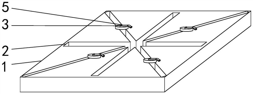
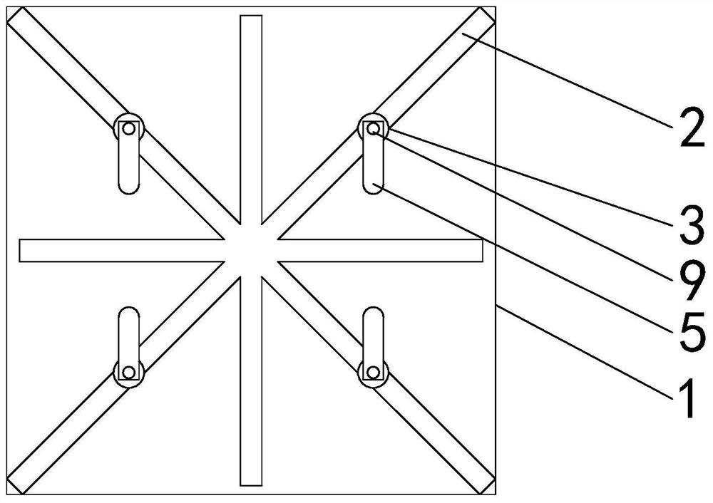
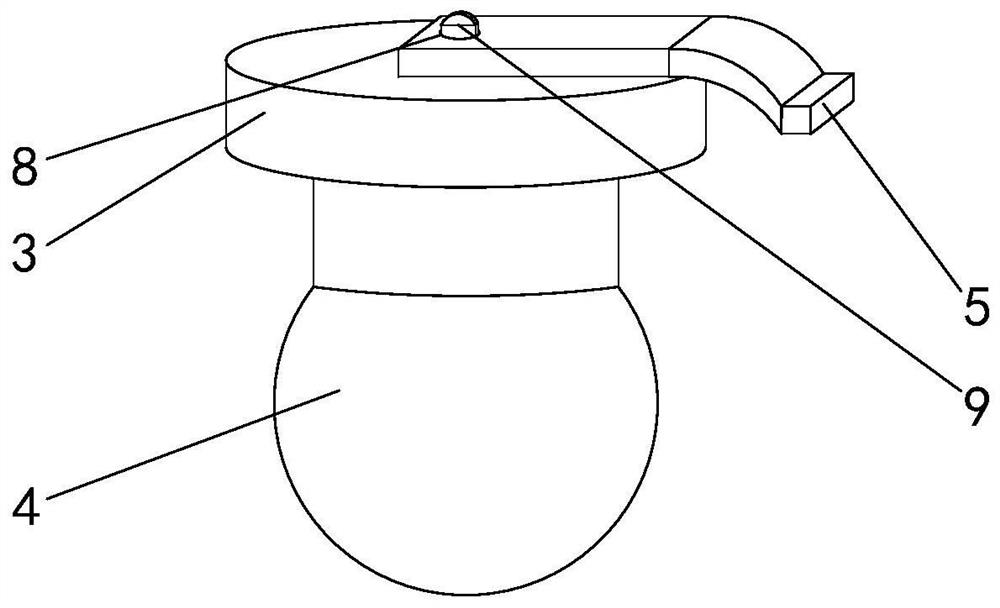
[0026] see Figure 1 to Figure 5 , the present invention provides a technical solution: a laser marking machine, including a laser emitting assembly and a processing table, the processing table includes a bottom plate 1 and a clamping assembly; In the movable groove 2; the clamping assembly includes a support plate 3, a sliding block 4 and a pressing piece 5; the sliding block 4 slides in the movable groove 2, and its shape adapts to the movable groove 2 and is set, and the sliding block 4 The upper end is connected to ...


PUM


Abstract

The invention relates to the technical field of laser marking machines, and discloses a laser marking machine. The laser marking machine comprises a laser emitting assembly and a processing table, and the processing table comprises a bottom plate and clamping assemblies; the clamping assemblies are movably installed in movable grooves formed in the upper end face of the bottom plate; the clamping assembles comprise supporting plates, sliding clamping blocks and pressing pieces; the sliding clamping blocks slide in the movable grooves, the shapes of the sliding clamping blocks are matched with the movable grooves, and the upper ends of the sliding clamping blocks are sequentially connected with the supporting plates and the pressing pieces; the lower surfaces of the supporting plates slide on the upper surface of the bottom plate; and the pressing pieces are connected to the supporting plates through connecting assemblies and used for pressing an object and preventing the object from moving. According to the laser marking machine, the sliding clamping blocks are placed along the movable grooves distributed in the shape like the Chinese character 'mi ', the positions of the clamping assemblies are adjusted in a sliding mode according to the shapes of special-shaped parts, then the relative height of the pressing pieces relative to the base is increased according to the thicknesses of the special-shaped parts, and rapid clamping of a workpiece is achieved.

Description

technical field [0001] The invention relates to the technical field of laser marking machines, in particular to a laser marking machine. Background technique [0002] With the development of science and technology and the improvement of residents' living standards, various manual DIY entertainment activities are gradually emerging. For laser marking technology, there are laser marking machines with various formats on the market. However, for some civilian laser marking machines Generally speaking, because the placement environment is too random, the placement of the workpiece to be processed and the abnormal movement during the processing process lead to defects in the DIY engraving on the object; There are also many offset phenomena. Therefore, some existing civilian laser marking machines have defects when they are used. [0003] For this reason, a laser marking machine is proposed. Contents of the invention [0004] The first object of the present invention is to prov...

Claims


Application Information

Patent Timeline
Patent Type & Authority Applications(China)
IPC IPC(8): B23K26/362B23K26/70B23K37/04
Inventor 黄涛夏勇辉
Owner 黄涛
Learn More