Efficient positioning welding equipment for alloy steel for high-end equipment manufacturing

A technology for positioning welding and alloy steel, applied in welding equipment, auxiliary welding equipment, welding/cutting auxiliary equipment, etc., which can solve the problems of eye hazard and difficult quality control.

Inactive Publication Date: 2021-04-16
南京俊士通商贸有限公司
View PDF0 Cites 3 Cited by
  • Summary
  • Abstract
  • Description
  • Claims
  • Application Information

AI Technical Summary

Problems solved by technology

[0004] In order to overcome the disadvantages of manually using welding tools to weld alloy steel, long-term artificial welding will cause damage to the e

Method used


Image

  • Efficient positioning welding equipment for alloy steel for high-end equipment manufacturing
  • Efficient positioning welding equipment for alloy steel for high-end equipment manufacturing
  • Efficient positioning welding equipment for alloy steel for high-end equipment manufacturing

Examples


Embodiment 1

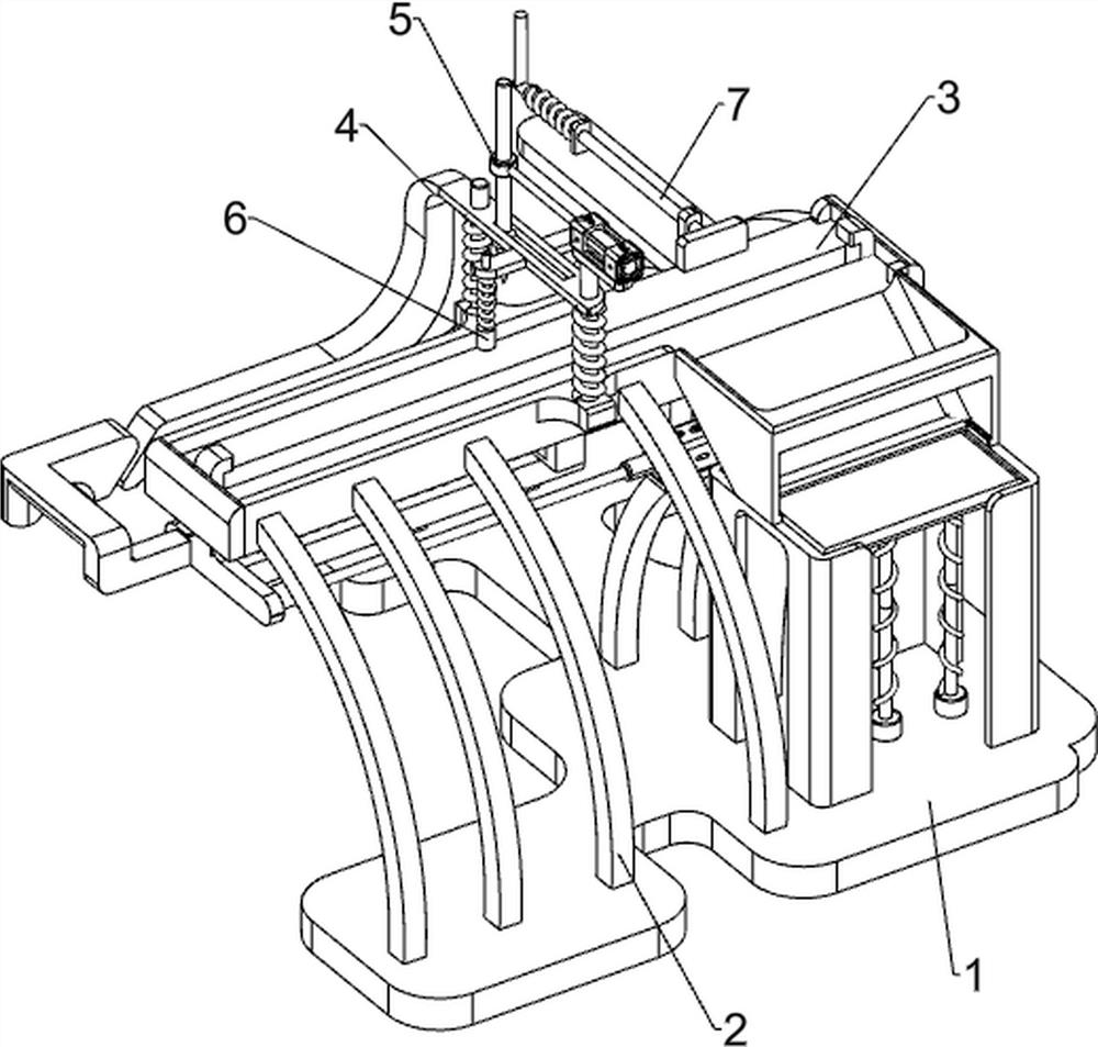
[0029] A high-end equipment manufacturing high-efficiency positioning welding equipment for alloy steel, such as figure 1 As shown, it includes a base plate 1, a bracket 2, a positioning mechanism 3, a pressing mechanism 4 and a welding mechanism 5. The base plate 1 is provided with a bracket 2, a positioning mechanism 3 is provided between the brackets 2, and a pressing mechanism 3 is provided in the middle of the positioning mechanism 3. Mechanism 4, a welding mechanism 5 is provided on the top of the left front side of the pressing mechanism 4 .

[0030] When people need to weld alloy steel, they can use this high-end equipment to manufacture high-efficiency positioning welding equipment for alloy steel. First, people need to put the alloy steel on the positioning mechanism 3, and then start the positioning mechanism 3, and the positioning mechanism 3 will drive The pressing mechanism 4 moves downwards, and then starts the welding mechanism 5. The welding mechanism 5 welds ...

Embodiment 2

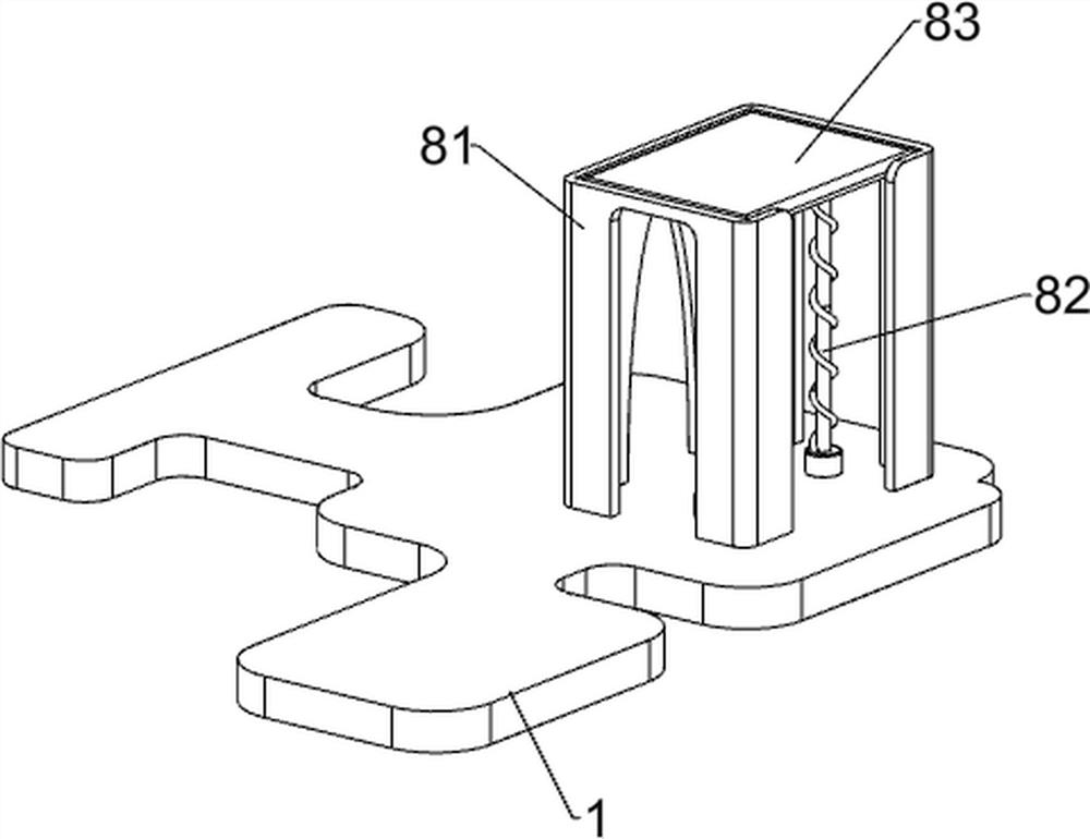
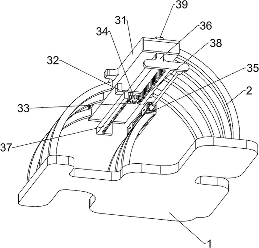
[0032] On the basis of Example 1, such as Figure 2-Figure 7 As shown, the positioning mechanism 3 includes a material holding plate 31, a mounting block 32, a rotating shaft 33, a spur gear 34, a first cylinder 35, a push plate 36, a first rack 37, a second rack 38 and a magnet 39. There is a material holding plate 31 between the side brackets 2, a mounting block 32 is provided at the middle bottom of the material holding plate 31, and a rotating shaft 33 is arranged at the middle bottom of the mounting block 32, and a spur gear 34 is provided on the rotating shaft 33. The middle support 2 The top is equipped with a first cylinder 35, the middle sliding type on the left side of the material holding plate 31 is provided with a push plate 36, the pushing plate 36 is connected with the telescopic rod of the first cylinder 35, and the middle sliding type on the right side of the material holding plate 31 is provided with a first tooth Bar 37, the upper right side of the first rac...


PUM


Abstract

The invention relates to efficient positioning welding equipment for alloy steel, in particular to efficient positioning welding equipment for alloy steel for high-end equipment manufacturing. The efficient positioning welding equipment for the alloy steel for high-end equipment manufacturing can achieve automatic welding, the quality of welded products is stable, and manpower resources are not wasted. The efficient positioning welding equipment for the alloy steel for high-end equipment manufacturing comprises a bottom plate, supports, a positioning mechanism, a pressing mechanism, a welding mechanism and the like, wherein the supports are arranged on the bottom plate, the positioning mechanism is arranged between the supports, the pressing mechanism is arranged in the middle of the positioning mechanism, and the welding mechanism is arranged at the top of the left front side of the pressing mechanism. According to the equipment, a telescopic rod of a first air cylinder moves leftwards to drive a push plate to move leftwards, so that a second rack is driven to move leftwards, then a straight gear is driven to rotate, the straight gear rotates to drive a first rack to move rightwards, a magnet on the right side can attract the welded alloy steel to the right side of a containing plate, and the positioning effect is achieved.

Description

technical field [0001] The invention relates to high-efficiency positioning welding equipment for alloy steel, in particular to high-efficiency positioning welding equipment for alloy steel for high-end equipment manufacturing. Background technique [0002] Alloy steel is steel added with other alloying elements in addition to iron and carbon. It has properties such as corrosion resistance, low temperature resistance and wear resistance. There are many types of alloy steel, which can be classified from different angles, such as alloy structural steel and Alloy tool steel, etc. In construction projects, alloy structural steel can be used to reduce structural weight and steel consumption. Using alloy steel to manufacture various mechanical parts can ensure the long-term use of parts. At present, in some alloy steel welding factories, Alloy steel is usually welded by manual welding tools. Manual welding for a long time will cause damage to the eyes, and quality control is diffi...

Claims


Application Information

Patent Timeline
IPC IPC(8): B23K37/00B23K37/02B23K37/04
Inventor 李俊士
Owner 南京俊士通商贸有限公司
Why Eureka
Try Eureka