High-temperature processing device for film production

A high-temperature processing and thin-film technology, which is applied in applications, household appliances, and other household appliances, can solve the problems of film material adhesion and difficulty in cleaning, and achieve the effect of enhancing stability

Active Publication Date: 2021-04-16
辽宁丰收塑业有限责任公司
View PDF33 Cites 0 Cited by
  • Summary
  • Abstract
  • Description
  • Claims
  • Application Information

AI Technical Summary

Problems solved by technology

[0005] The technical problem to be solved in the present invention is to provide a high-temperature processing device for film production, the purpose of which is to separate the film material from the inner wall of the nozzle, and solve the problem that the film material adheres to the nozzle after cooling and is difficult to clean

Method used


Image

  • High-temperature processing device for film production
  • High-temperature processing device for film production
  • High-temperature processing device for film production

Examples


Embodiment 1

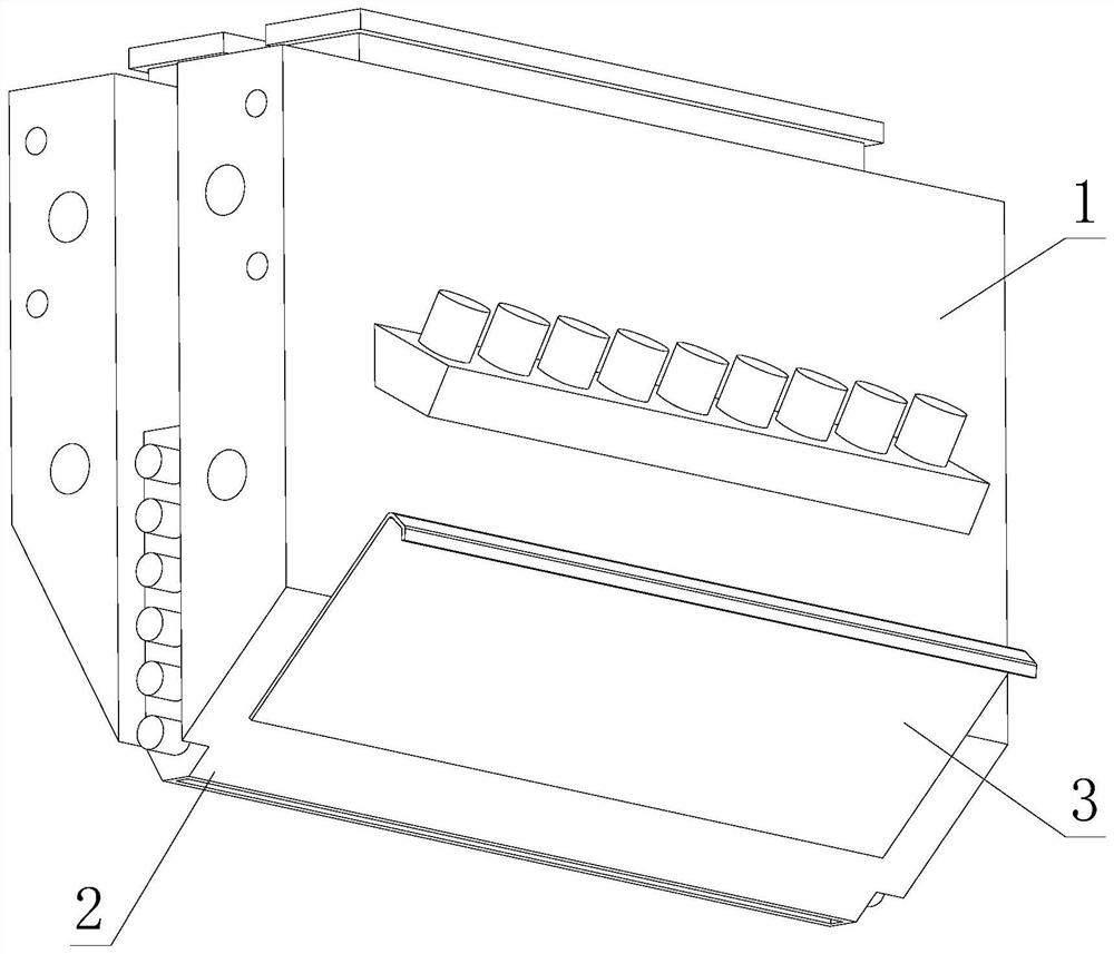
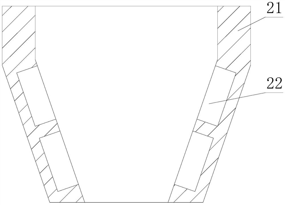
[0023] Such as figure 1 - image 3 As shown, the present invention provides a high-temperature processing device for film production, including a body 1, a nozzle 2 is arranged at the lower end of the body 1, a side plate 3 is arranged on one side of the lower end of the body 1, and a nozzle is arranged inside the nozzle 2 21 , both sides inside the nozzle 21 are fixedly connected with detachment structures 22 .

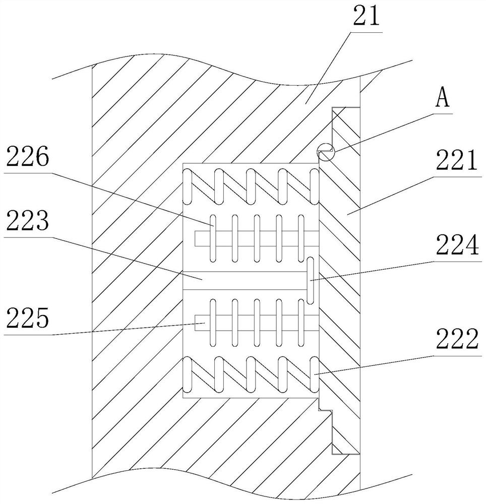
[0024] Wherein, the interior of the breakaway structure 22 is provided with a vibration plate 221, the side of the vibration plate 221 close to the nozzle 21 is fixedly connected with a vibration rod 225, the outer surface of the vibration rod 225 is fixedly connected with a vibration pick 226, and the nozzle 21 is close to the side of the vibration plate 221. One side is fixedly connected with a fixed rod 223 , and one end of the fixed rod 223 close to the vibration plate 221 is fixedly connected with a dial 224 , and a spring 222 is fixedly connected between the v...

Embodiment 2

[0027] Such as Figure 4-5 As shown, on the basis of Embodiment 1, the present invention provides a technical solution: the inside of the vibration plate 221 is provided with a detachment block 2211, and the inside of the detachment block 2211 is provided with an air cavity 2212, and the upper and lower ends of the air cavity 2212 are fixed. Connected with the connecting rod 2213 , the end of the air chamber 2212 away from the nozzle 21 is provided with a circular arc protrusion 2214 , and an inner air chamber 2215 is provided inside the circular arc protrusion 2214 .

[0028] Wherein, the vibrating plate 221 is designed in a convex shape, the edge of the narrower end of the vibrating plate 221 is provided with a chamfer, the edge where the nozzle 21 contacts with the corner of the vibrating plate 221 is provided with a chamfer, and the arc protrusion 2214 is half Circular design, the distance between every two arc protrusions 2214 is relatively large.


PUM


Abstract

The invention discloses a high-temperature processing device for film production, and relates to the technical field of film production. The high-temperature processing device comprises a machine body, a spray head is arranged at the lower end of the machine body, a side plate is arranged at one side of the lower end of the machine body, and a nozzle is arranged in the spray head. Through the arrangement of a vibration poking piece and a poking plate, during moving, the vibration poking piece is poked through the poking plate to vibrate, so that a gap is generated between a thin film raw material and a vibration plate, a thin film is separated from the vibration plate, and later cleaning of the film is facilitated; and through the separated design of the vibration plate and the nozzle, in the heating process, due to separation of the vibration plate, in the heating process, due to separation of the vibration plate and mutual expansion and extrusion between the vibration plate and a separation structure in the heating process, the expansion degree of the separation structure is larger than that of the nozzle, so that the springback range of the vibration plate is larger in the subsequent cooling and cold contraction process, and the vibration plate is conveniently separated from the thin film raw material.

Description

technical field [0001] The invention relates to a high-temperature processing device, relates to the technical field of film production, in particular to a high-temperature processing device for film production. Background technique [0002] In the film production process, the raw material of the film needs to be melted at high temperature, then extruded through a nozzle, and then extruded into a film. There are following problems at prior art: [0003] 1. In the prior art, after the nozzle extrudes the film raw material, there is a problem that with the cooling of the device, a part of the film raw material will remain inside the nozzle and block the nozzle; [0004] 2. In the prior art, it will increase the difficulty of cleaning for some production workers, and then fail to achieve the original intention of convenient production, and the applicability of the processing device will become poor, so structural innovation is required to solve specific problems. Contents of...

Claims


Application Information

Patent Timeline
Patent Type & Authority Applications(China)
IPC IPC(8): B29C48/27B29C48/305B29C48/08B29L7/00
Inventor 王士凯
Owner 辽宁丰收塑业有限责任公司
Why Eureka
Try Eureka