Unmanned aerial vehicle recovery device and control method

A recycling device and drone technology, applied in the field of drones, can solve the problems of low work efficiency and long time, and achieve the effect of reducing labor intensity, avoiding manual assembly, and avoiding manual operation.

Pending Publication Date: 2021-04-16
湖南省地面无人装备工程研究中心有限责任公司
View PDF7 Cites 2 Cited by
  • Summary
  • Abstract
  • Description
  • Claims
  • Application Information

AI Technical Summary

Problems solved by technology

[0002] In the recovery of drones, the skyhook recovery method has the advantages of high efficiency, short work preparation time, and low recovery site requirements, and is widely used on land or ships and other platforms with tight space. However, the skyhook recovery device requires on-site Assembling, disassembling or unfolding and folding requires the cooperation of multiple people, which has the problems of long time consumption and low work efficiency

Method used


Image

  • Unmanned aerial vehicle recovery device and control method
  • Unmanned aerial vehicle recovery device and control method
  • Unmanned aerial vehicle recovery device and control method

Examples


Embodiment 1

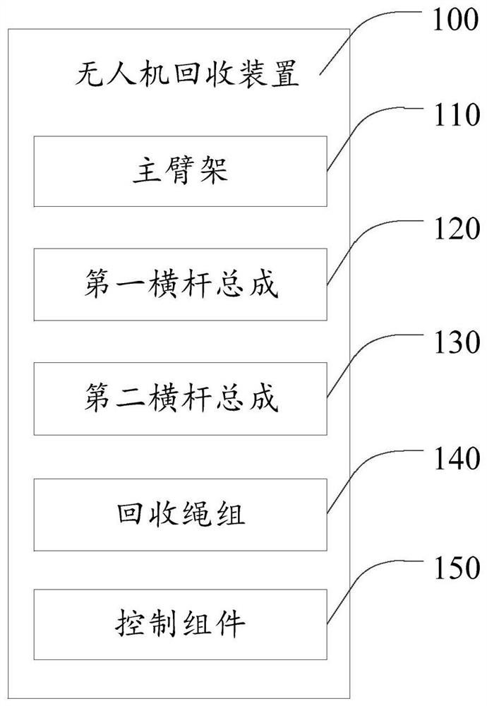
[0063] Such as figure 1 As shown, this embodiment provides a UAV recovery device 100, including: a main boom 110, a first crossbar assembly 120, a second crossbar assembly 130, a recovery rope set 140 and a control assembly 150, the main The boom 110 is provided with a first driving assembly 112, and the first driving assembly 112 is used to realize the expansion or retraction of the main boom 110; the first crossbar assembly 120 is provided with a second driving assembly 122, and the second driving assembly 122 is used to realize The first crossbar assembly 120 is deployed or retracted; the second crossbar assembly 130 is provided with a third drive assembly 132, and the third drive assembly 132 is used to realize the deployment or retraction of the second crossbar assembly 130; one end of the recovery rope set 140 The first crossbar assembly 120 is connected, and the other end is connected to the second crossbar assembly 130; the control assembly 150 is used to control the f...

Embodiment 2

[0066] Such as figure 2 , Figure 4 and Figure 6 As shown, in addition to the technical features of the above-mentioned embodiments, this embodiment further includes the following technical features:

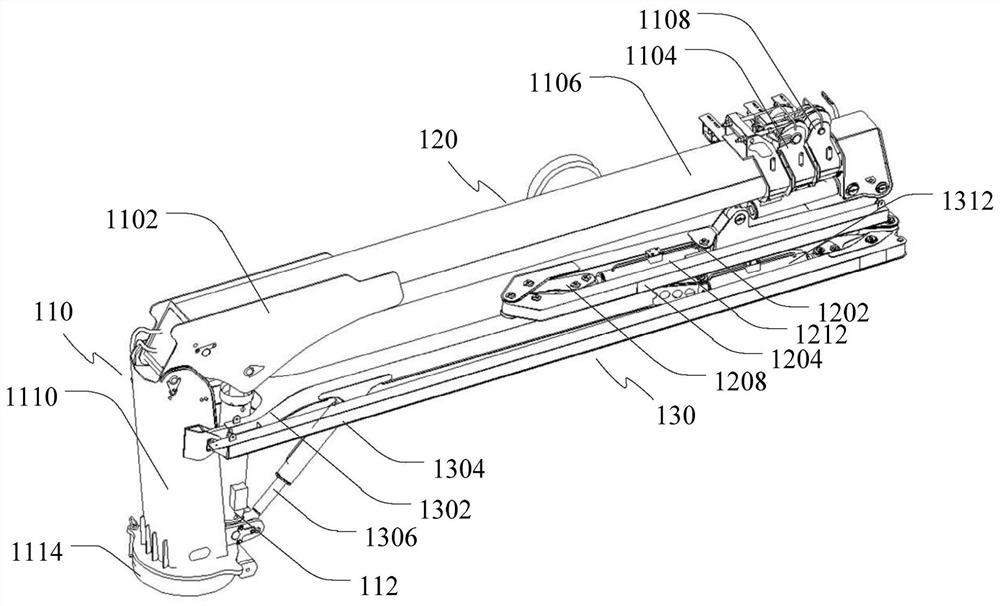
[0067] The first crossbar assembly 120 includes: a first section arm 1202 and a second section arm 1204, wherein, one end of the first section arm 1202 is connected with the main boom frame 110, and the other end is connected with the second section arm 1204, and the second section arm 1204 connects the recovery rope set 140 .

[0068] For example, the first crossbar assembly 120 is designed as a two-stage structure, including the first section arm 1202 and the second section arm 1204. When in use, the second section arm 1204 is unfolded to form a The angle can be about 180 degrees.

[0069] For another example, the first joint 1202 and the second joint 1204 may be hinged.

Embodiment 3

[0071] Such as Figure 4 , Figure 6 and Figure 9 As shown, in addition to the technical features of the above-mentioned embodiments, this embodiment further includes the following technical features:

[0072] The second driving assembly 122 includes: a first driving part 1206, a first connecting rod 1208, a second connecting rod 1210 and a second driving part 1212. One end of the first driving part 1206 is connected to the main arm frame 110, and the other end is connected to the first joint The arm 1202 is connected; one end of the first connecting rod 1208 is connected with the first section arm 1202, and the other end is connected with the second driving part 1212; one end of the second connecting rod 1210 is connected with the second section arm 1204, and the other end is connected with the second driving part 1212 Connection; one end of the second driving part 1212 is connected with the first joint 1202, and the other end is connected with the first connecting rod 120...


PUM


Abstract

The invention provides an unmanned aerial vehicle recovery device and a control method. The unmanned aerial vehicle recovery device comprises a main arm frame, a first cross rod assembly, a second cross rod assembly, a recovery rope group and a control component. The main arm frame is provided with a first driving component, and the first driving component is used for realizing unfolding or folding of the main arm frame; the first cross rod assembly is provided with a second driving assembly, and the second driving assembly is used for realizing unfolding or folding of the first cross rod assembly; the second cross rod assembly is provided with a third driving assembly, and the third driving assembly is used for realizing unfolding or folding of the second cross rod assembly; one end of the recovery rope group is connected with the first cross rod assembly, and the other end is connected with the second cross rod assembly; the control assembly is used for controlling the first driving assembly, the second driving assembly and the third driving assembly. According to the technical scheme, the main arm frame, the first transverse rod assembly and the second transverse rod assembly can be automatically unfolded and folded, manual intervention is not needed, the labor intensity is effectively reduced, and the use efficiency is improved.

Description

technical field [0001] The present invention relates to the technical field of unmanned aerial vehicles, in particular, to an unmanned aerial vehicle recovery device and a control method. Background technique [0002] In the recovery of drones, the skyhook recovery method has the advantages of high efficiency, short work preparation time, and low recovery site requirements, and is widely used on land or ships and other platforms with tight space. However, the skyhook recovery device requires on-site Assembling, disassembling, or unfolding and folding requires the cooperation of multiple people, which has the problems of long time consumption and low work efficiency. Contents of the invention [0003] The present invention aims to solve at least one of the above technical problems. [0004] For this reason, the first object of the present invention is to provide a drone recovery device. [0005] The second object of the present invention is to provide a method for control...

Claims


Application Information

Patent Timeline
Patent Type & Authority Applications(China)
IPC IPC(8): B64F1/02
Inventor 刘璟赵光明王剑波张平
Owner 湖南省地面无人装备工程研究中心有限责任公司
Why Eureka
Try Eureka