Direct-acting automatic limiting device

A technology of automatic limit and limit device, applied in storage devices, transportation and packaging, etc., can solve the problems of low degree of automation, difficult maintenance and many supporting equipment, etc., to achieve high degree of automation, low use and maintenance costs, and simplification The effect of system composition

Active Publication Date: 2021-04-16
SHENYANG SIASUN ROBOT & AUTOMATION
View PDF7 Cites 0 Cited by
  • Summary
  • Abstract
  • Description
  • Claims
  • Application Information

AI Technical Summary

Problems solved by technology

[0004] In view of the above problems, the purpose of the present invention is to provide a direct-acting automatic limit device to solve the actual problems of the existing automatic storage system, such as low automation, difficult maintenance, many supporting equipment, and complicated systems. Limits for pallets in transfer storage

Method used


Image

  • Direct-acting automatic limiting device
  • Direct-acting automatic limiting device
  • Direct-acting automatic limiting device

Examples


Embodiment 1

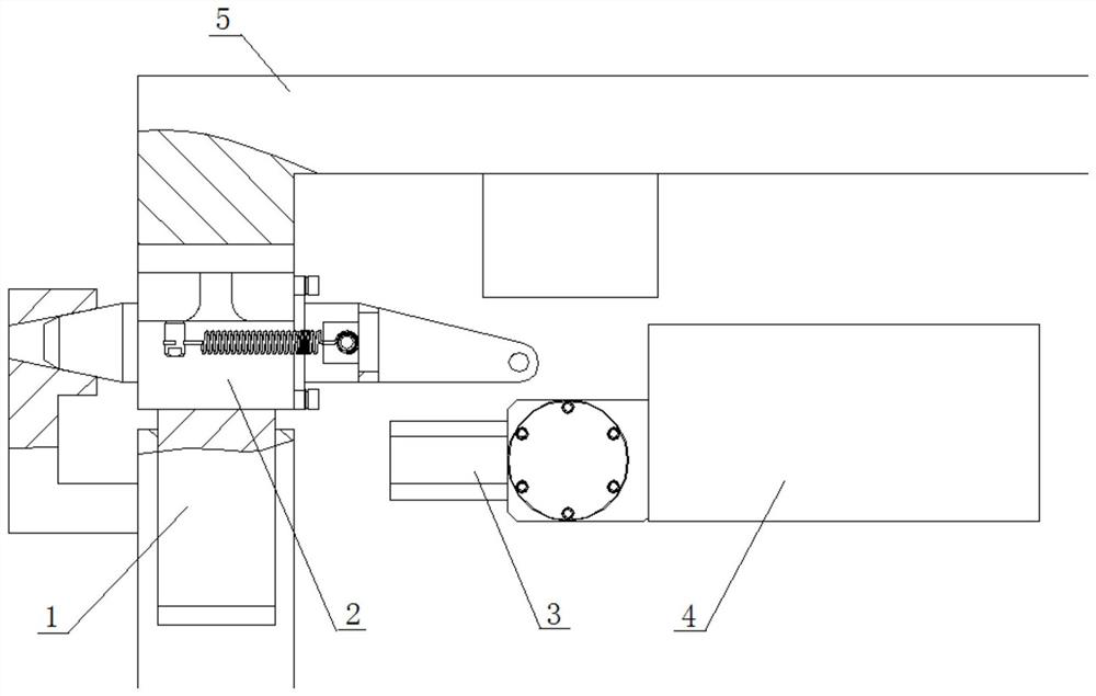
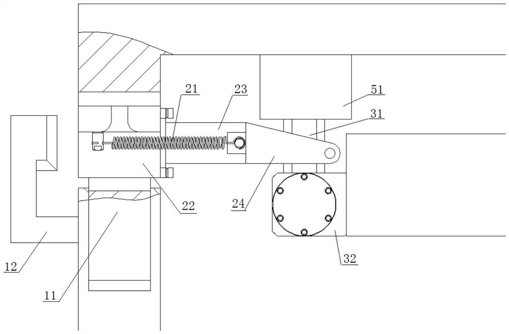
[0030] Such as Figure 1-3 As shown, the swing unlocking device 3 includes a swing shaft 31, a fixed seat 32 and a swing drive device 33, wherein the fixed seat 32 is arranged on the horizontal drive device 4, the swing drive device 33 is arranged on the fixed seat 32, and the output end is connected to the swing shaft 31 is vertically connected, and the swing shaft 31 is driven by the swing drive device 33 to swing, thereby pulling the linear motion limiter 2 to realize the unlocking of the tray 5 .

[0031] Further, the swing direction of the swing shaft 31 is perpendicular to the conveying direction of the storage roller table 1 .

[0032] In this embodiment, the swing driving device 33 is a servo motor, and the horizontal driving device 4 is a telescopic fork. The rollers 11 of the storage roller table 1 are used to carry the trays 5 .

[0033] The direct motion limiting device 2 includes a reset device 21, a guide fixing seat 22 and a limit pin 23, wherein the guide fix...

Embodiment 2

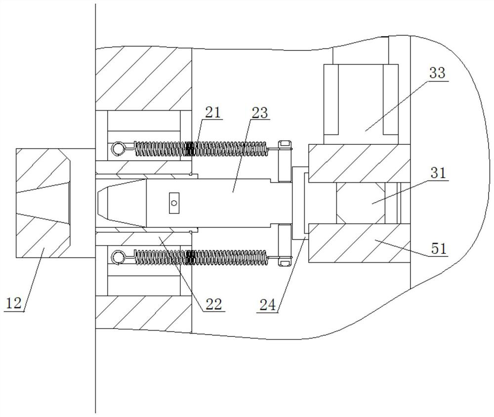
[0043] Such as Figure 4-6 As shown, the swing unlocking device 3 includes a swing shaft 31, a fixed seat 32 and a swing drive device 33, wherein the fixed seat 32 is arranged on the horizontal drive device 4, the swing drive device 33 is arranged on the fixed seat 32, and the output end is connected to the swing shaft 31 is vertically connected, and the swing shaft 31 is driven by the swing drive device 33 to swing, thereby pushing the linear motion limiter 2 to realize the unlocking of the tray 5 .

[0044] In this embodiment, the swing driving device 33 is a servo motor, and the horizontal driving device 4 is a telescopic fork. The rollers 11 of the storage roller table 1 are used to carry the trays 5 .

[0045]Straight motion limiter 2 comprises resetting device 21, guide fixed seat 22 and limit pin 23, wherein guide fixed seat 22 is arranged on the side of storage roller table 1, guide hole is offered along the vertical direction on guide fixed seat 22, limit position T...


PUM


Abstract

The invention relates to a tray limiting device of an automatic storage system, in particular to a direct-acting automatic limiting device. The device comprises a direct-acting limiting device, a swing unlocking device and a horizontal driving device, wherein the direct-acting limiting device is arranged on a tray or a storage roller way and used for positioning the position of the tray on the storage roller way; the swing unlocking device is arranged on the horizontal driving device and relieves limitation of the direct-acting limiting device on the tray through swing; and the horizontal driving device is used for driving the swing unlocking device to an unlocking position and is connected with the tray through the swing unlocking device to drive the swing unlocking device to provide power for transferring of the tray. Automatic limiting or limiting relieving of the tray can be achieved, and reliable fixing of the tray and goods is guaranteed; and a direct-acting structure is adopted, structural design is simplified, stability and reliability are improved, manufacturing difficulty and machining cost are reduced, and use and maintenance cost is low.

Description

technical field [0001] The invention relates to a pallet limiting device of an automatic storage system, in particular to a direct-acting automatic limiting device. Background technique [0002] In order to increase the utilization rate of the storage warehouse and improve the efficiency of product storage, the current automatic storage system mostly adopts the three-dimensional storage mode; in the three-dimensional storage mode, due to the low energy consumption of horizontal transfer and high safety, it is more and more widely used. In the horizontal transfer mode, it is necessary to set a limit device to solve the limit of the pallet. At present, there are two types of pallet limit devices for horizontal transfer three-dimensional warehouses: active and passive; the active type needs to be equipped with a power source in the three-dimensional warehouse, which has high construction costs, high supporting costs, difficult use and maintenance, and low system reliability; T...

Claims


Application Information

Patent Timeline
Patent Type & Authority Applications(China)
IPC IPC(8): B65G1/04
Inventor 裴新平李国文邓嘉骐王洪伟王建奇李峥王左坤
Owner SHENYANG SIASUN ROBOT & AUTOMATION
Why Eureka
Try Eureka