
Automatic board clamping device and locating clamping method thereof

A splint and automatic technology, applied in the direction of conveyor control device, transportation and packaging, conveyor, etc., can solve the problems of many parts of the width adjustment mechanism, easy to damage the substrate, etc., to ensure fast adjustment accuracy, reduce costs, and improve work efficiency Effect

Active Publication Date: 2021-04-16
深圳市易安锐自动化设备有限公司
View PDF9 Cites 8 Cited by
  • Summary
  • Abstract
  • Description
  • Claims
  • Application Information

AI Technical Summary

Problems solved by technology

[0004] The purpose of the present invention is to provide an automatic splint device that solves the problem of PCB clamping with no buffer structure that is easy to damage the substrate and the wide-ranging mechanism has many parts. Another purpose of the present invention is to provide a device that can improve production efficiency and product quality. The positioning and clamping method of the automatic splint device

Method used


Image

  • Automatic board clamping device and locating clamping method thereof
  • Automatic board clamping device and locating clamping method thereof
  • Automatic board clamping device and locating clamping method thereof

Examples


Embodiment Construction

[0043]The present invention will be further detailed in connection with the accompanying drawings:

[0044]The preferred embodiments of the present invention will be described in detail below with reference to the accompanying drawings to better understand the scope of the invention in the art, whereby the advantages and characteristics of the present invention will be more clearly defined. The direction term mentioned in the present invention, for example, "on", "next", "before", "left", "right", "top", "bottom", etc., only refer to additional graphics direction. Therefore, the direction term used is used to illustrate and understand the invention, not to limit the invention.

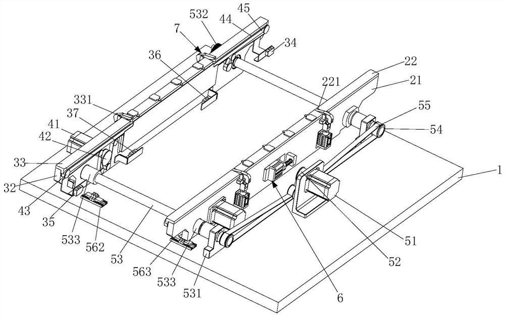
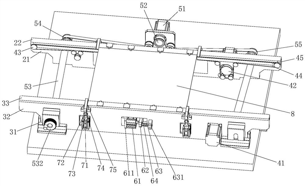
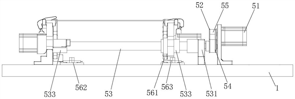
[0045]Seefigure 1 ,figure 2 As shown, an automatic splint device comprising a bottom plate 1, a movable track assembly 2, a fixed track assembly, a width adjustment mechanism 5, a control component, a control assembly, a control component, and an active rail assembly, a width adjustment mechanism 5, a control comp...


PUM


Abstract

The invention relates to an automatic board clamping device and a locating clamping method thereof. The automatic board clamping device comprises a baseboard, a movable track assembly, a fixed track assembly, a width adjusting mechanism and a control assembly, and a PCB jacking and clamping mechanism and a PCB locating mechanism are arranged on the movable track assembly and the fixed track assembly; a PCB induction mechanism is further arranged between the movable track assembly and the fixed track assembly; the fixed track assembly and the movable track assembly are arranged on the baseboard, and the fixed track assembly and the width adjusting mechanism are fixedly arranged on the baseboard; the movable track assembly is movably installed on a width adjusting lead screw of the width adjusting mechanism; and the movable track assembly is transversely moved relative to the baseboard under the action of the width adjusting mechanism, and used for adjusting the distance between the two track assemblies. The automatic board clamping device is matched with the locating clamping method, so that PCBs in different widths can be efficiently, stably and accurately processed, and the product quality of the PCBs is improved.

Description

Technical field[0001]The present invention relates to the field of PCB board processing, and more particularly to a positioning clamping method of an automatic splint device and an automatic splint device.Background technique[0002]The PCB board is printed circuit board, also known as printed circuit board, printed circuit board, referred to as printed board, it is an important electronic component, which is a support of electronic components, and its processing quality and efficiency are critical. The existing automatic clamping substrate is mostly rising through the cylinder control clamp, directly topped mechanism, such a structure without any buffer, and easily damage the substrate in some cases, while the equipment work is easy to produce dust. There is an impact on the processing of the PCB board, affecting product quality;[0003]In addition, the existing broader mechanism is adjusted by the structure of the lead wires through the linear slide rail. Although the structure can re...

Claims


Application Information

Patent Timeline
IPC IPC(8): B65G47/22B65G43/08B65G23/04B65G23/44B65G41/00B65G15/12
Inventor 徐美祥
Owner 深圳市易安锐自动化设备有限公司
Learn More